Kiri
| Dokumendiregister | Transpordiamet |
| Viit | 13.7-3/24/11323-1 |
| Registreeritud | 27.06.2024 |
| Sünkroonitud | 02.07.2024 |
| Liik | Sissetulev kiri |
| Funktsioon | 13.7 Aeronavigatsiooniteenuse ja lennuliikluse korraldamine (ATM/ANS) |
| Sari | 13.7-3 Lennuliiklusalane kirjavahetus |
| Toimik | 13.7-3/2024 |
| Juurdepääsupiirang | Avalik |
| Adressaat | EVENTECH OÜ |
| Saabumis/saatmisviis | EVENTECH OÜ |
| Vastutaja | Eve Härm (Users, Lennundusteenistus, Lennuliiklusteeninduse ja lennuväljade osakond) |
| Originaal | Ava uues aknas |
Failid

Tere!
Teie poole soovitas pöörduda Kea Toi, kelle poole pöördus minu kolleeg 2022. aasta juulis laserite taotlusega sama festivali raames.
Kirjutan Teile seoses sooviga taotleda luba laserite kasutamiseks 11.-14. juuli Pärnu Rannapargis.
Kasutame festivalil 16tk 10W laserit ning 6tk 20W laserit (seadmete manuaalid koos tehniliste andmetega on lisatud kirja manusesse).
Lasereid kasutatakse:
- 11. juuli alates kell 20.00 kuni 12. juuli kell 6.00 laserite turvatsoonide seadistamiseks ning laserite programmeerimiseks festivali ajaks.
- 12. juuli kell 18.00 kuni 13. juuli kell 01.00 festivali show ajal.
- 13. juuli kell 18.00 kuni 14. juuli kell 01.00 festivali show ajal.
Kiirte divergens:
- 10W laser: divergens < 1.0 mrad
- 20W laser: divergens < 1.0 mrad
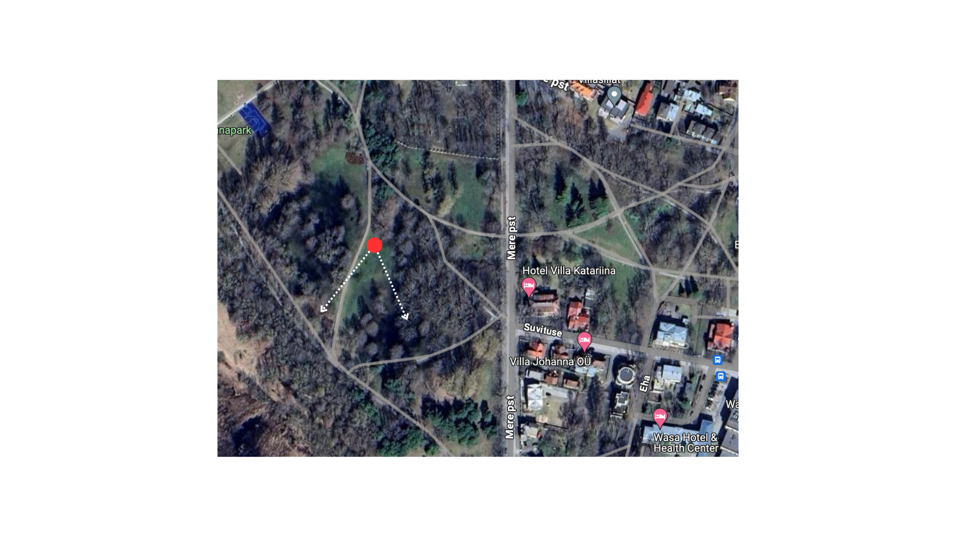
Asimuut: vahemik 160°-240°
Laserite kiired on maapinna suhtes 0°-60°. Festivali ala on piiratud puudega ning turvatsoonid piiravad laserite lekkimise võimaluse üle puude.
Manuses on joonis, kus on piltlikult näidatud laserite suund kaardil. Punasega on märgitud lava asukoht, kus laserid asetsevad ning nooltega välja toodud kiirte maksimaalne laius. Joonis on illustratiivne.
Lisan siia ka täpse lava asukoha Google Mapsi lingiga:
Lava asukoht
Kui vajate veel täiendavat infot, siis edastan selle esimesel võimalusel vastavalt Teie vajadustele.
| Tervitades Hugo Johannes Visnapuu Projektijuht EVENTECH OÜ |
| • +372 56603952 | +372 655 5444 • [email protected] • www.eventech.ee • Gaasi tee 5, Lehmja 75306, Estonia |
Manual / Bedienungsanleitung / Mode d´emploi
RTI PIKO Series PIKO RGB 20 | PIKO RGB 26 OPSL
PIKO RYGB 31 OPSL | PIKO G 20 OPSL
Please spend a few minutes to read this manual fully before operating this laser!
Bitte lesen Sie diese Bedienungsanleitung sorgfältig vor Inbetriebnahme dieses Showlasersystems!
Avant d’utiliser cet appareil pour la première fois nous vous recommandons de lire cette notice d’utilisation!
10/2019
English Deutsch Français
Manual: RTI PIKO Series
page 2 / 57
Rechtlicher Hinweis: Die Firma Ray Technologies GmbH behält sich das Recht vor, Änderungen an ihren Produk- ten vorzunehmen, die der technischen Weiterentwicklung dienen. Diese Änderungen werden nicht notwendigerweise in jedem Einzelfall dokumentiert. Diese Betriebsanleitung und die darin enthaltenen Informationen wurden mit der gebotenen Sorgfalt zusammengestellt. Die Firma Laserworld (Switzerland) AG und ihr Tochterunternehmen, die Ray Technologies GmbH, übernehmen jedoch keine Gewähr für Druckfehler, andere Fehler oder daraus entste- hende Schäden. Die in dieser Bedienungsanleitung genannten Marken und Produktnamen sind Warenzeichen oder eingetragene Warenzeichen der jeweiligen Titelhalter.
Legal notice:
Thank you for purchasing this Ray Technologies product. Due to continual product developments and technical improvements, Ray Technologies GmbH reserves the right to make modifications to its products. This manual and its content have been made with due care but neither Laserworld (Switzer- land) AG nor its subsidiary Ray Technologies GmbH cannot, however, take any responsibility for any errors, omissions or any resulting damages forthwith. The brands and product names mentioned in this manual are trade marks or registered trade marks of their respective owners.
Information juridique :
L’entreprise Ray Technologies GmbH se réserve le droit d’effectuer des modifications con- cernant leurs produits et ainsi de répondre au développement technique. Ces modifications ne seront pas nécessairement annoncées en tout cas spécifique. Ce mode d’emploi et les in- formations contenues dedans ont été établis avec le soin minutieux qui s’impose dans ce cas. Laserworld (Switzerland) AG et sa filiale Ray Technologies GmbH ne pourra pas être tenue responsable pour d’éventuelles erreurs d’impression ou dommages en résultants. En cas de doutes, veuillez toujours contacter Laserworld (Switzerland) AG . Les noms de marques et de produits utilisés dans ce mode d’emploi sont des marques de fabrique ou des marques déposées.
L’utilisation est réservée à un usage professionnel selon décret n°2007-665 du 2 mai 2007 relatif à la sécurité des appareils à laser sortant! Article 4 bis : « Les usages spécifiques autorisés pour les appareils à laser sortant d’une classe supérieure à 2 sont les usages professionnels suivants : (…) 9° Spectacle et affichage : Toutes les applications de trajectoire, de visualisation, de projection ou de reproduction d’images en deux ou trois dimensions. »
Manual: RTI PIKO Series
page 3 / 57
Content:
1. Product and package contents
2. Preliminary warning notices
3. Initial operations, safety instructions
4. Working on the device
5. Service notes
6. Warnings and other notices on the device
7. Device connections
8. Operation
9. Remote control pad
Final statement
Technical data sheet
Laser specifications
Manual: RTI PIKO Series
page 4 / 57
1. Product and package contents
Please check if all listed parts are included and undamaged. Included in delivery:
1 x laser projector 1 x manual 1 x powercon power cable 1 x 3-channel adapter (only for PIKO RGB 26 & PIKO RYGB 31)
3. Initial operations, safety instructions
1. Make sure to use correct voltage; see in- formation on device & in this manual.
2. Make sure that the device is not connec- ted to mains during installation.
3. Installation has to be done by technical experienced and qualified persons ac- cording to safety regulations of the res- pective country.
4. Always ensure that maximum permis- sible exposure (MPE) is not exceeded in areas accessible to the public or members of staff.
5. In some countries an additional ins- pection by technical control institutes could be necessary.
6. The power supply should be easily acces- sible.
7. When installing the laser mount it with a minimum distance of 15 cm from walls and objects.
8. For safe setup e.g. on walls or ceilings please use a safety cord. The safety cord should be able to withstand tenfold the weight of the device. Please follow the accident prevention regulations of pro- fessional associations and/or comparable regulations for accident prevention.
9. If the device has been exposed to great temperature changes, do not switch it on immediately.
10. Never use dimmer, RC or other electroni- cally switched sockets. Whenever possib- le, do not use the laser projector together with large appliances (especially fog ma-
2. Preliminary warning notices
1. Please use this device only according to these operating instructions.
2. Do not use the device if there are any visible damages on housing, connector panels, power supplies or power cords.
3. Never look directly into the light source of a laser projector. Danger of damage to the eyes or even blindness in extreme circumstances!
4. Do not operate the device at high humidity, in the rain or in dusty environments. 5. Protect device against dripping or splashing water. Do not place any liquid filled
containers near to this device.
Any warranty claims are void if the warranty label is removed or tampered with in any way.
Manual: RTI PIKO Series
page 5 / 57
chines) on the same mains!
11. Ensure sufficient ventilation and do not place the device on any warm or heat radiating surface. Especially the venti- lation openings must not be covered!
12. Ensure that device does not get over- heated. Make sure that the device is not exposed to spotlights (especially moving heads). Heat of spotlights could overheat laser in a little while and leads to a de- graadation.
4. Working on the device
1. This product has no user serviceable parts inside and should only be maintained and serviced by a qualified engineer.
2. Be sure that the mains plug is not connected to the power supply while installing the device.
3. Take off all reflecting things like rings, watches etc. befo- re starting to work with or at the projector.
4. Only use non-reflecting tools to work on device.
5. Wear protective clothing (like goggles, gloves etc.) according to laser power and wavelength of the laser.
5. Service notes
• Moisture and heat can reduce lifetime of the laser system dramatically and expires any warranty claim.
• Quick on/off switching of this device will reduce durability of the laser diode dra- matically.
• Avoid sharp knocks and shocks to this device and ensure sufficient protection during transportation. Look after your La- serworld product.
• To increase durability of your laser, protect device against overheating: - Always ensure sufficient ventilation. - Do not face spotlights (especially mo-
ving heads) to the device. - Check temperature after approx. 30
minutes with each new installation. If necessary install the projector at a
place with different temperature. - Keep the device dry. Protect it from
moisture, rain and damp. - Switch off device when it is not nee-
ded. Diodes are switched on and can wear out even if there is no visible la- ser output.
• Please ensure the fans and heatsinks are clear from dust and debris otherwise the risk of overheating may occur. If the unit and airways appear to be blocked then please contact a qualified service engi- neer to maintain and service the product.
• Removal of the warranty label as well as damages to the device caused by improper handling, neglect of the sa- fety instructions and service notes will void the warranty.
Manual: RTI PIKO Series
page 6 / 57
7. Device connections
Mains connection
ILDA in
Interlock out
configuration
Emission LED
DMX out (optional)
DMX in (optional)
6. Warnings and other notices on the device
Laser radiation! Avoid exposure to beam.
Laser class 4
Caution of radiation if cover is removed
Power supply & consumption
Model type
Wavelength
Output power
Production year
Please read manual before operation
Only for indoor use!
Fuse 4At
ILDA out
Interlock in
Manual: RTI PIKO Series
page 7 / 57
8. Operation
Please note that when the ‘Emission LED’ is on, the laser is enabled and may emit laser light. There is one LED on the remote control pad, one on the rear side and one on the front side of the device. The LED on the device flashes if the device is connected to the power supply. The LED on the control pad flashes if the device is switched on.
8.1. Powers supply
Make sure that your device is provided with the correct voltage. Wrong voltage could lead to irreparable damages. Please find the correct voltage data in the synoptical table at the end of this manual. It must be ensured that the device is not directed to people or inflammable objects during installation.
8.2. ILDA control
To control your device connect it via ILDA cables to an interface/controller. The pinout and maximum voltages for the ILDA standard Sub-D connectors are:
Pin Signal Voltage
1 X + (horizontal) + 5.0 V 2 Y + (vertical) + 5.0 V 4 Interlock A - 5 Red + + 2.5 V 6 Green + + 2.5 V 7 Blue + + 2.5 V 8 (RTI PIKO RGB 22) Light Red2+ + 2.5 V 9 (RTI PIKO RGB 22) Cyan+ + 2.5 V 13 Shutter + 5.0 V 14 X – (horizontal) - 5.0 V 15 Y – (vertical) - 5.0 V 17 Interlock B - 18 Red - - 2.5 V 19 Green - - 2.5 V 20 Blue - - 2.5 V 21 (RTI PIKO RGB 22) Light Red2- - 2.5 V 22 (RTI PIKO RGB 22) Cyan- -2.5 V 25 Ground -
Manual: RTI PIKO Series
page 8 / 57
8.3. Channels (RTI PIKO RGB 26 / RTI PIKO RYGB 31):
8.3.1. 3-Channel Adapter
This adapter is required to operate the 5 or 6 color channel laser system with an interface which otherwise supports only 3 color channels. If there are only 3 output channels instead of 5 or 6, this adapter is required to get the full power of the laser system.
In case you are using a controller with just three color outputs (RGB) you can use the provi- ded D-Sub connector to wire both red together and blue and cyan together. You just need to plug the connector into the ILDA OUT plug. Important: If you are using this D-Sub connector you cannot use controllers with more than three channels. Otherwise the controller hardware would pull down the intensity of red and blue! If you have a controller with more than three channels you need to patch the colors in the software and should not use this D-Sub connector.
Channel Colors / Wavelengths:
1 658nm
2 530nm
3 447nm
4 638nm
5 462nm The above table shows the assignment of the channels with red and blue. Only the first thr- ree channels are occupied by RGB, the remaining three channels can be used freely.
8.3.2. External Interlock
The Remote Control Pad has a built-in emergency stop. If there is the need for an external interlock, please disconnect the Remote Control Pad and use the ‚Control‘ connection (RJ-45 connector) to connect it with an external interlock.
8.4. Browser operation instructions
The RTI PIKO laser series can be configured via browser over LAN / WiFi. This is possible through computer, laptop, but also through mobile phones or tablets, if the control signal is sent over WiFi via a WiFi capable Router / Access Point. Devices connected to the same local network as the laser systems are capable to accessing the dedicated laser user interface through a previ- ously configured IP address or an automatically assigned IP address from a DHCP server.
If only one single laser shall be configured and the laser system is directly connected to the control computer by LAN cable, please continue with chapter 8.1.2.1.
Manual: RTI PIKO Series
page 9 / 57
8.4.1. DHCP mode - automatic address setting
Requirements: Standard router with DHCP functionality (e.g.: D-Link Wireless AC750 DualBand Easy Router).
The DHCP mode can be used for the configuration of one or more laser devices.
a. Connect the laser device(s) to the router with an ethernet cable (CAT-5 or higher). Make sure that DHCP mode is activated on the router and that it is capable to provide an auto- matic IP address (see the manual of your router).
b. Connect the router to the computer or the laptop with another ethernet cable (CAT-5 or higher). It can be possible that the WiFi mode of a compatible router is also instantly ac- cessible. In this case it can be possible, that mobile devices can already be used without the need of preliminary configuration through a wired setup. To ensure everything works well it is recommended to set up a wired configuration first. This is how the setup looks like. It is also possible to connect several RTI PIKO lasers to one router:
Connection with DHCP routerRTI PIKO laser
Eth ern
et c able
Ethernet cable Computer
Router
c. Type the IP address or name of your router into the web browser of your computer to access the administration menu of the router setup. Please see the manual of the router to find out how this feature can be accessed. The administration interface of the router usually has a certain user interface showing all connected devices within the network. Check for the IP addresses that have been assigned per laser system and write them down for fu- ture use. Each laser can be configured by entering this IP address to the browser address bar.
d. If there are no laser units visible on this overview page, make sure that each laser is pow- ered up properly, that the ethernet cables are connected correctly and that only standard network cable were used (do not use cross cable!).
e. If it is not possible to access the router administration interface or if the LAN con- nection shows errors, continue with chapter 8.4.2 „How to set the computer to DHCP mode“
Manual: RTI PIKO Series
page 10 / 57
8.4.2. How to configure the computer to work in DHCP mode
Only follow these steps if issues with accessing the router through DHCP arise. The chapter can be skipped if the computer can already communicate through DHCP and there is access to the router administrative menu. a. Click on the Windows start button and navigate to the control panel, click on „Network
and Internet“ and find „Network and Sharing center“, click on it. There should be only one active connection, otherwise deactivate second active connection as it may lead to irritations. Double click on the active connection name (after label „Connections:“)
b. The „Ethernet Status“ window opens. Click on „Properties“, and head for the „Internet Pro- tocol Version 4 (TCP/IPv4)“. Double click it and select „Properties“. The following window allows for setting the DHCP mode. If you want to enable DHCP, make sure „Obtain an IP address automatically“ is selected, as well as „Obtain DNS server address automatically“.
1
2 3 4 After having done the settings, try the steps described in chapter 8.4.1 again.
Manual: RTI PIKO Series
page 11 / 57
8.4.2.1. Static IP mode
Depending on the number of laser systems that shall be used, there are two options for connecting the computer to the laser. If only one laser system shall be used, a normal direct network cable between the laser system and the computer is sufficient. This can of course be extended with a normal switch. This option is discussed in chapter 8.4.2.1. (a).
The other option is that there are more than two laser systems, that shall be connected to the computer at the same time. To find more details on this kind of setup, please head to chapter 8.4.2.1. (b).
a. Direct connection
RTI PIKO laser Computer
192.168.1.100 192.168.1.123
Ethernet cable
e.g.
Laser device as RTI PIKO has it‘s own default IP adress 192.168.1.00. In order to establish the connection, connect the laser device through the ethernet cable directly with the laptop or PC.
The computer must be set to a static IP address in the same address space than the RTI PIKO laser , but it MUST NOT be the same IP address, for example 192.168.1.10 or 192.168.1.35 are OK. See chapter 8.4.2.2 on how to set IP address for the PC properly.
After setting the unique IP at your computer, use previously set IP address to access the laser configuration panel by typing it to the browser address bar of the computer or any other (mobile) device that is properly connected to the same local area network as the RTI PIKO la- ser system. The factory default is: 192.168.1.00. In order to access the browser interface type default login and password (Login: admin, Password: admin). It is recommended to change the default login and password to prevent unauthorised access.
In order to change the default IP address of the laser device, connect to the user panel as described above. Click on the tab „More“ and then on the word „System/IP Setup“ in the user panel in order to change the static IP address. This IP address has NO EFFECT if the laser is connected through DHCP (as described in chapter 8.1.1)
To change IP address, click here.
Manual: RTI PIKO Series
page 12 / 57
b. Connection through switch
Requirements: Standard network switch
The computer must be set to a static IP address in the same address space than the RTI PIKO laser(s), but it MUST NOT be the same IP address, for example 192.168.1.10 or 192.168.1.35 are OK. See chapter 8.4.2.2. on how to set IP address for the PC properly.
In case of having more than one RTI PIKO laser in the local network, ensure to set a unique IP address for each one of them. To do so, it is necessary that each laser is directly connected to the computer as described in chapter 8.1.2.1. (a). After having set individual IP addresses per laser, all lasers and the computer can be wired as shown below:
Switch
Ethernet c able
Ethernet cable
RTI PIKO laser 1 Computer
Ethernet cable
RTI PIKO laser 2
8.4.2.2. How to set a static IP address
a. Click on the Windows start button and navigate to your control panel, click on „Network and Internet“ and find „Network and Sharing center“, click on it. There should be only one active connection, otherwise deactivate the second active connection as it may lead to irritations. Double click on the active connection name (after label „Connections:“)
b. The „Ethernet Status“ window opens. Click on „Properties“, and look for the „Internet Protocol Version 4 (TCP/IPv4)“. Click and select „Properties“. The following window allows for specifying a static IP address. Subnet mask is 255.255.255.0 (do not change).
Manual: RTI PIKO Series
page 13 / 57
1
2 3 4
8.4.3. Browser interface
In the upper left corner of the browser interface it is possible to switch between the different operation statuses: As standard, the laser is „OFF“. To get any output from the system, it is necessary to change the status to „ON ILDA“.
Laser „OFF“ button. Laser „On ILDA“ button.
Manual: RTI PIKO Series
page 14 / 57
8.4.3.1. Color intensity
This tab allows for changing the color intensity per color channel by sliders.
8.4.3.2. Device status
The „Status“ tab shows selected statistics on the projector status like temperature values, interlock status as well as XY galvo positioning.
Manual: RTI PIKO Series
page 15 / 57
8.4.3.3. User access configuration
The „User Setup“ tab provides options for changing, adding or deleting users as well as chan- ging the users passwords.
8.4.3.4. Load firmware updates / configuration
The „Firmware/Config“ tab allows to upgrade an existing firmware.
Manual: RTI PIKO Series
page 16 / 57
8.4.3.5. Advanced settings
The „Advanced“ tab allows for setting various projector features like safety behavior etc.
8.4.3.6. Scanner settings
The size as well as the position of the projection can be adjusted with the horizontal faders. Shift specifies the offset position, Size specifies the scale of the projection on X and Y axis. It is also possible to flip the projection by using negative values.
Manual: RTI PIKO Series
page 17 / 57
9. Remote Control Pad (optional available)
If the device is equipped with the optional detachable remote control pad, the following ima- ges explain the use of the pad. Touch the screen to change the settings.
9.1. Starting sequence
9.2. Main Menu
Emergency Stop button:
Press button to inter- rupt laser output
Emission Laser on button:
The device is enabled if the diode is lit.
Touchscreen
Key switch with key:
Insert key and turn it to ‚on‘ to start the device.
Laser on / off: Device is enabled / disabled
Version and tempera- ture display
Laser status, amperage & interlock status display
Laser on / internal: The internal access to an e.g. SD-card is enabled
Laser on / ILDA in: The external access through ILDA is ena- bled
Color & Scan Setup: Use these buttons for co- lor or scan settings
DMX, Adv. and Setup: Use these buttons for the color or scan settings. Adv. Setup only for factory defaults!
Back: Use this button to return back.
Status display
Manual: RTI PIKO Series
page 18 / 57
9.3. Color Settings:
+ / -: Use these buttons to change the color intensity
Colors: Please note that only implemented laser sources can be changed in their itensity. If there is e.g. no yellow laser source in- stalled in your device you can‘t change the itensity of the yellow color. The intensity change only applies per single laser source and does not change mixed colors. Please use your software to change mixed color in- tensities.
In case you have a RTI PIKO RGB 22 (RTI PIKO Rainbow Series) you can adjust the light red intensity with the yellow slider and the cyan intensity with the light blue slider.
9.4. Scanner Settings:
X Size horizontal: Use these buttons to change the horizontal size of the outputY Size vertical:
Use these buttons to change the vertical size of the output
Y Shift up/down: Use these buttons to change the vertical shift of the output
X Shift left/right: Use these buttons to change the horizontal shift of the output
Manual: RTI PIKO Series
page 19 / 57
Final statement
RTI products are tested and product packaging is inspected before leaving our warehouse. Users must to follow the local safety regulations and warnings within this manual and adhere to any regulations within its place of use. Damages through inappropriate use will void any liability or warranty of our products. Due to continual product developments, please check for the latest update of this product manual at www.laserworld.com. If you do have any further questions, then please contact your dealer/place of purchase or use our contact section on our website. For service issues, please contact your dealer/place of purchase and ensure only genuine Laserworld spare parts are used in any service repairs.
Errors and Omissions excepted and products are subject to change.
Laserworld (Switzerland) AG Kreuzlingerstrasse 5 8574 Lengwil Switzerland Registered office: 8574 Lengwil / Switzerland Company number: CH-440.3.020.548-6 Commercial Registry Kanton Thurgau CEO: Martin Werner VAT no. (Switzerland): 683 180 UID (Switzerland): CHE-113.954.889 VAT no. (Germany): DE 258030001 WEEE-Reg.-No. (Germany): DE 90759352
www.laserworld.com [email protected]
representative according to EMVG: Ray Technologies GmbH Managing Director: Martin Werner Mühlbachweg 2 83626 Valley / Germany
Manual: RTI PIKO Series
page 20 / 57
Inhaltverzeichnis:
1. Lieferumfang & Hinweise
2. Einleitende Warnhinweise
3. Schritte zur Inbetriebnahme, Sicherheitshinweise
4. Sicherheitshinweise für Arbeiten am Gerät
5. Pflege- und Wartungshinweise
6. Warnhinweise und Spezifikationen am Gerät
7. Geräteanschlüsse & Bedienelemente
8. Bedienung
9. Remote Control Pad
Abschließende Erklärung
Technische Daten
Laserleistungsdaten
Manual: RTI PIKO Series
page 21 / 57
1. Lieferumfang & Hinweise
Bitte prüfen Sie, ob Sie die Lieferung vollständig erhalten haben und die Ware unbeschädigt ist. Im Lieferumfang enthalten sind:
1 x Laserprojektor 1 x Bedienungsanleitung 1 x Powercon Kabel zur Stromversorgung 1 x 3-Kanal-Adapter (nur für PIKO RGB 26 & PIKO RYGB 31)
3. Schritte zur Inbetriebnahme, Sicherheitshinweise:
1. Stellen Sie sicher, dass Sie das Gerät mit der richtigen Spannung betreiben (siehe Angaben auf dem Gerät bzw. in dieser Bedienungsanleitung).
2. Stellen Sie sicher, dass das Gerät während der Installation nicht mit dem Strom- netz verbunden ist.
3. Der Laser darf nur von technisch versier- tem Fachpersonal gemäss der im jewei- ligen Land geltenden Sicherheitsbestim- mungen installiert werden.
4. Die am Betriebsort geforderten Sicher- heitsabstände zwischen Gerät und Publikum, bzw. maximal zulässige Be- strahlungswerte (MZB), müssen immer eingehalten werden.
5. In bestimmten Ländern kann zusätzlich eine Abnahme durch ein technisches Überwachungsinstitut erforderlich sein.
6. Die Stromversorgung zugänglich halten.
7. Halten Sie bei der Installation einen Min- destabstand von 15 cm zur Wand und an- deren Objekten ein.
8. Bei einer Festinstallation an Wand, Decke o.ä., sichern Sie den Laser zusätzllich mit einem Sicherheitsfangseil. Das Fang- seil sollte mindestens dem 10-fachen Gewicht des Geräts standhalten können. Im Übrigen beachten Sie die Unfallverhü- tungsvorschriften der Berufsgenossen- schaften und/oder vergleichbare Rege- lungen zur Unfallverhütung.
2. Einleitende Warnhinweise
1. Betreiben Sie das Gerät nur gemäß dieser Bedienungsanleitung.
2. Benutzen Sie das Gerät nicht, wenn sichtbare Beschädigungen am Gehäuse, den An- schlussfeldern oder vor allem an den Stromversorgungsbuchsen oder -kabeln vorliegen.
3. Niemals direkt in den Strahl des austretenden Lasers blicken. Dies könnte zu irreparab- len Schäden an den Augen und der Netzhaut führen. Erblindungsgefahr!
4. Gerät nicht bei hoher Luftfeuchtigkeit, Regen oder in staubiger Umgebung betreiben.
5. Vor Tropf-/Spritzwasser schützen, keine mit Flüssigkeit gefüllten Gefäße auf oder neben dem Gerät abstellen.
Bei Entfernung oder Manipulation des Garantielabels erlischt jeglicher Anspruch auf Gewährleistung!
Manual: RTI PIKO Series
page 22 / 57
9. Wenn das Gerät großen Temperatur- schwankungen ausgesetzt war, schalten Sie es nicht unmittelbar danach an.
10. Benutzen Sie niemals Dimmer-, Funk- oder andere elektronisch gesteuerten Steckdosen! Falls möglich benutzen Sie den Laser nicht zusammen mit anderen großen elektrischen Verbrauchern (ins- besondere Nebelmaschinen) auf dersel- ben Leitung/Phase!
11. Sorgen Sie immer für eine ausreichende Belüftung und stellen Sie das Gerät auf keine warmen oder wärmeabstrahlen- den Untergründe. Die Belüftungsöffnun- gen dürfen nicht verdeckt sein.
12. Stellen Sie auch sicher, dass das Gerät nicht zu heiß wird und dass es nicht dem Strahl von Scheinwerfern ausgesetzt wird (insbesondere bei beweglichen Schein- werfern!). Die Wärme dieser Strahler kann den Laser überhitzen.
4. Sicherheitshinweise für Arbeiten am Gerät
1. Service- und Reparaturarbeiten sollten ausschließlich von qualifi- ziertem Fachpersonal durchgeführt werden.
2. Stellen Sie sicher, dass der Netzstecker gezogen ist, wenn Sie am Gerät hantieren bzw. es installieren.
3. Vor Arbeiten am Gerät alle reflektierenden Gegenstände wie Ringe, Uhren etc. ablegen.
4. Verwenden Sie für Arbeiten am Gerät ausschließlich nicht reflektierendes Werkzeug.
5. Tragen Sie auf die Laserstärke und -wellenlängen angepasste Schutzbekleidung (Schutzbrille, Handschuhe, etc.).
5. Pflege- und Wartungshinweise
• Feuchtigkeit und Hitze können die Le- bensdauer des Lasersystems stark ver- kürzen und führen zum Erlöschen des Gewährleistungsanspruchs.
• Das Gerät nicht schnell hintereinander Ein- und Ausstecken/-schalten, da dies die Lebensdauer der Laserdiode erheb- lich verkürzen kann!
• Beim Transport des Lasers jegliche Erschütterung oder Schläge vermeiden. Bitte das Produkt bestmöglich schützen. Laserworld bietet entsprechendes Equip- ment an.
• Um die Lebensdauer Ihres Lasers zu erhö- hen, schützen Sie das Gerät vor Überhit- zung:
Manual: RTI PIKO Series
page 23 / 57
- Immer für ausreichende Belüftung sorgen.
- Keine Scheinwerfer (insbesondere kopfbewegte) auf das Gerät richten.
- Bei jeder Neuinstallation nach ca. 30 Minuten die Gerätetemperatur prü- fen und gegebenenfalls das Gerät an einem kühleren/besser belüfteten Standort platzieren.
- Halten Sie das Gerät trocken und schützen Sie es vor Nässe, Regen und Spritzwasser.
• Schalten Sie das Gerät aus, wenn es nicht benutzt wird. Trennen Sie hierzu das Netzteil von der Stromversorgung. Auch wenn die Diode nicht leuchtet: Sie ist in Betrieb, solange das Gerät angeschaltet ist.
• Lüfter und Kühlkörper (Kühlrippen usw.) müssen frei von Staubansammlungen und Ablagerungen sein, da sonst die Ge- fahr des Überhitzens droht und jegliche Gewährleistung erlischt. Bitte wenden Sie sich an qualifizierte Fachpersonen.
• Durch das Entfernen des Garantiela- bels erlischt jeglicher Anspruch auf Gewährleistung. Schäden am Gerät, die durch unsachgemäßer Handha- bung, Nichtbeachtung der Sicher- heits-, Pflege- und Wartungshinweise entstehen besteht kein Gewährleis- tungsanspruch.
6. Warnhinweise und Spezifikationen am Gerät
Laserstrahlung! Nicht dem Strahl aussetzen.
Laserklasse 4
Laserstrahlung bei geöffnetem Gehäuse
Stromversor- gung- und verbrauch
Produktname
Wellenlänge
Ausgangsleis- tung
Produktions- jahr
Vor Inbetriebnahme Bedienungsanleitung lesen!
Nur in geschlossenen Räumen betreiben!
Manual: RTI PIKO Series
page 24 / 57
7. Geräteanschlüsse & Bedienelemente
8. Bedienung
Das Gerät ist betriebsbereit, wenn die ‚Emissions-LEDs‘ leuchten. Der Projektor kann dann La- serlicht ausstrahlen. Jeweils ein Emissions-LED befindet sich auf dem Remote Control Pad, auf der Rückseite, sowie auf der Vorderseite des Gerätes. Die LED auf der Rückseite des Gerätes leuchtet, wenn das Gerät an die Stromversorgung angeschlossen ist, die LED auf dem Remote Control Pad leuchtet, wenn das Gerät angeschaltet ist.
8.1. Stromversorgung (AC)
Die Stromversogung sollte mit einer Überladungssicherung und mit einer Erdung versehen werden. Es muss darauf geachtet werden, dass das Gerät mit der richtigen Spannung versorgt wird, da die falsche Spannung zu irreparablen Schäden am Gerät führen kann. Die Spannungs- daten entnehmen Sie bitte der Übersichtstabelle am Ende dieser Bedienungsanleitung. Stel- len Sie sicher, dass die Vorderseite des Lasers (Bereich des Strahlaustritts) während des An- schließens an die Stromversorgung nicht auf Personen oder entflammbare Objekte gerichtet ist.
Anschluss für die Stromversorgung
ILDA Eingang
Interlock out
Konfiguration
Emissions- LED
DMX out (optional)
DMX in (optional)
Sicherung 4At
ILDA Ausgang
Interlock in
Manual: RTI PIKO Series
page 25 / 57
8.2. ILDA-Ansteuerung
Um das Gerät über ILDA anzusteuern, muss dieses über ILDA-Kabel mit einem Interface / Con- troller verbunden werden. Die Pinbelegung und die maximale Spannung für den ILDA-Betrieb finden sich in folgender Tabelle:
Pin Signal Spannung
1 X + (horizontal) + 5.0 V
2 Y + (vertikal) + 5.0 V
4 Interlock A -
5 Rot + + 2.5 V
6 Grün + + 2.5 V
7 Blau + + 2.5 V
8 Hellrot 2+
9 Cyan +
13 Shutter + 5.0 V
14 X – (horizontal) - 5.0 V
15 Y – (vertikal) - 5.0 V
17 Interlock B -
18 Rot - - 2.5 V
19 Grün - - 2.5 V
20 Blau - - 2.5 V
21 Hellrot 2-
22 Cyan -
25 Ground -
Manual: RTI PIKO Series
page 26 / 57
8.3. Kanäle (RTI PIKO RGB 26 / RTI PIKO RYGB 31):
8.3.1. 3-Kanal-Adapter
Dieser Adapter wird benötigt, um das 5- bzw. 6-Farbkanal-Lasersystem mit einem Interface betreiben zu können, das ansonsten nur 3 Farbkanäle unterstützt. Wenn anstatt von 5 oder 6 nur 3 Ausgabekanäle vorhanden sind, dann wird dieser Adapter benötigt, um die volle Leistung des Lasersystems zu erhalten. Für den Fall, dass ein Controller mit nur drei Farbausgängen (RGB) genutzt wird, sollte der im Lieferumfang enthaltene D-Sub-Adapter verwendet werden, um beide Rottöne sowie Blau und Cyan zusammenzuführen. Hierzu muss lediglich der Adapter mit der ILDA-OUT-Buchse verbunden werden. Achtung: Wenn der D-Sub-Adapter verwendet wird, können keine Controller mit mehr als drei Kanälen genutzt werden, da ansonsten die Controller-Hardware die Leistung von Rot und Blau vermindert! Wenn ein Controller mit mehr als drei Kanälen verwendet wird, müssen die Farben über die Software angepasst werden. Der mitgelieferte D-Sub-Adapter sollte dann nicht verwendet werden.
Kanal Farben / Wellenlängen:
1 658nm
2 530nm
3 447nm
4 638nm
5 462nm Die obige Tabelle verdeutlicht die Belegung der Kanäle mit Rot und Blau. Dabei werden lediglich die ersten drei Kanäle von RGB belegt, die übrigen drei Kanäle können frei belegt werden.
8.3.2. Externer Interlock
Das Remote Control Pad besitzt einen integrierten Notaus. Wird ein externer Interlock benö- tigen, kann das Kabel des Remote Control Pads vom Gerät abgenommen werden. Über den ‚Control‘-Anschluss (RJ-45) kann ein externer Interlock angeschlossen werden.
Manual: RTI PIKO Series
page 27 / 57
8.4. Browser Interface Betriebsanleitung
Die RTI PIKO Serie können mittels Browser über LAN / WLAN konfiguriert werden. Mobile Ge- räte mit WLAN-Funktion und Browser wie z.B. Smartphones, Tablets, etc., die mit demselben Netzwerk wie der Laser verbunden sind, können über vorher konfigurierte IP-Adressen auf das User-Interface des Lasers zugreifen.
8.4.1. DHCP-Modus - Automatische IP-Adressen-Konfiguration
Voraussetzung: Router mit DHCP Funktion (bspw.: D-Link Wireless AC750 DualBand Easy Rou- ter)
a. Zunächst ein Ethernet-Kabel CAT-5 oder höher mit dem Laser und anschließend mit dem Router verbinden. Der DHCP-Modus des Routers muss aktiviert und in der Lage sein, automatische IP-Adressen zu vergeben (hierzu bitte auch die Bedienungsanleitung des Routers beachten).
b. Nun ein weiteres Ethernet-Kabel (CAT-5 oder höher)mit dem Router und anschließend mit einem Computer oder Laptop verbinden. Es kann sein, dass der LAN Modus des Rou- ters standardmäßig bereits aktiviert ist. In diesem Fall ist es auch möglich, die Verbindung über WLAN aufzubauen und mobile Geräte können ggf. ohne vorherige Konfiguration über Netzwerkkabel bereits auf den Laser zugreifen. Das Setup ist unten dargestellt. Es ist auch möglich mehrere Laser an einen Router zu verbinden.
Verbindung mit DHCP RouterPIKO Laser
Netzwerk KabelNetzwerk Kabel Computer
Router
c. Die IP-Adresse oder den Namen des Routers in den Webbrowser des Computers einge- ben um den Administrationsbereich des Lasers aufzurufen. Die IP Adresse des jeweiligen lasers kann über die Benutzeroberfläche des Routers herausgefunden werden - bitte dazu die Bedienungsanleitung des Routers beachten. Normalerweise gibt es im Menü des Routers einen Reiter, der alle verbundenen Geräte zeigt.
d. Falls auf der Übersichtsseite des Routers keine verbundenen Geräte angezeigt werden, bitte die Betriebsbereitschaft der Laser überprüfen - jeder Laser muss betriebsbereit sein, damit er vom Router erkannt werden kann. Sollte der Laser trotzdem nicht erkannt werden, bitte die Netzwerkverkabelung prüfen.
e. Sollte es nicht möglich sein die Benutzeroberfläche des Routers aufzurufen oder falls die Netzwerkverbindung einen Fehler anzeigt, bitte mit Kapitel 8.4.1. fortfahren!
Manual: RTI PIKO Series
page 28 / 57
8.4.2. Wie wird der DHCP Modus im PC eingestellt?
Dieses Kapitel muss nur beachtet werden, sollte das Administrationsmenü des Routers nicht über den Browser aufgerufen werden können. Andernfalls kann dieses Kapitel übersprungen werden.
a. Bitte über den Windows-Start-Button die Systemsteuerung und dann „Netzwerk und Internet“ auswählen. Dort befindet sich das „Netzwerk- und Freigabecenter“, das ausge- wählt werden muss. Es sollte nur eine aktive Verbindung angezeigt werden. Gegebenen- falls müssen weitere aktive Verbindungen deaktiviert werden, um Irritationen zu vermei- den. Bitte den blau unterlegten Verbindungs-Namen auswählen (hinter „Verbindungen“).
b. Das Status-Fenster öffnet sich. Nun über „Eigenschaften“ das „Internetprotokoll Version 4 (TCP/IPv4)“ auswählen. Doppelklicken und „Eigenschaften“ auswählen. Das geöffnete Fenster ermöglicht es auf automatische Adresszuweisung umzustellen. Um den DHCP zu aktiviert, müssen „IP-Adresse automatisch beziehen“ sowie „DNS-Serveradresse automa- tisch beziehen“ ausgewählt sein.
1
2 3 4
Manual: RTI PIKO Series
page 29 / 57
8.4.2.1. Betriebsmodus Statische IP
Je nachdem wie viele Laser genutzt werden sollen gibt es verschiedene Varianten den die Laser mit dem Computer zu verbinden. Soll nur ein einzelner Laser genutzt werden reicht eine direkte Netzwerkverbindung zwischend em Laser und dem Computer aus. Natürlich kann die Leitung auch durch herkömmliche Switches verlängert werden. Diese option wird im Kapitel 8.4.2.1. (a) aufgezeigt.
Die andere Variante ist, dass mehere Lasersysteme von einem Computer gesteuert werden sollen. -Weitere Details zu dieser Variante finden sich im Kapitel 8.4.2.1. (b).
a. Direkte Verbindung
RTI PIKO Laser Computer
192.168.1.100 192.168.1.123
Netzwerk Kabel
Beispiel
Die RTI PIKO Showlaser Serie haben standardmäßig die IP Adresse 192.168.1.100 eingestellt. Um die Verbindung herzustellen und die IP Adresse zu konfigurieren, muss das Lasersystem über ein Ethernet-Kabel direkt mit dem Laptop oder PC verbunden werden.
Der Computer muss mit einer statischen IP-Adresse aus dem selben Adressraum wie die des RTI PIKO Lasers versehen werden. Im Adressraum, in dem sich das Lasersystem befindet, darf eine IP-Adresse nur ein Mal vergeben werden (zum Beispiel 192.168.1.10 oder 192.168.1.35). Für weitere Informationen bitte das Kapitel 8.4.2.2. beachten.
Um die Standard-IP-Adresse des Showlasers zu ändern, muss der Computer über ein Ethernet- Kabel mit dem Lasersystem verbunden sein. Danach die Standard-IP-Adresse 192.168.1.100 in den Webbrowser eingeben. Um auf den Webbrowser zugreifen zu können ist ein Benutzerna- me und Passwort (Standardeinstellung: Benutzername: admin, Passwort: admin) notwendig. Es wird empfohlen Standard-Login und Passwort zu ändern, um unautorisierten Zugriff zu verhindern. Im Webbrowser erscheint nun die Benutzeroberfläche des Lasersystems.
Um die IP-Adresse des Lasers zu ändern bitte auf „More“ klicken und dann auf „System/IP Se- tup“. Die statische IP Adresse des Lasers hat KEINE GÜLTIGKEIT wenn der Laser im DHCP Modus betrieben wird (wie im Kapitel 8.1.11 beschrieben).
Um die IP-Adresse zu ändern, hier klicken
Manual: RTI PIKO Series
page 30 / 57
b. Anschluss über einen Switch Voraussetzung: Herkömmlicher Netzwerk-Switch
Die IP-Adresse des Lasers muss im gleichen Adressbereich wie der Computer liegen. Das be- deutet, dass wenn das Lasersystem die IP-Adresse 192.168.1.10 besitzt, die IP-Adresse des Computers im Bereich zwischen 192.168.1.1 und 192.168.1.254 liegen muss - der Computer darf dabei aber nicht die selbe IP-Adresse wie das Lasersystems haben! Das Subnetz muss ebenfalls das selbe sein (255.255.255.0).
Sollten sich mehr als ein Lasersytem im lokalen Netzwerk befinden, muss jedes System eine eindeutige IP-Adresse besitzen (siehe auch Kapitel 8.1.2.1. (b)), damit die richtige IP-Adresse für das Lasersystem eingestellt werden kann. Nachdem jeder Laser eine individuelle IP Adres- se hat, sieht das Setup so aus:
Switch
Neztw erk KabelNetzwerk Kabel
RTI PIKO Laser 1 Computer
N etzw
erk Kabel
RTI PIKO Laser 2
8.4.2.2. Wie wird eine statische IP-Adresse eingestellt?
a. Bitte über den Windows-Start-Button die Systemsteuerung und dann „Netzwerk und Internet“ auswählen. Dort befindet sich das „Netzwerk- und Freigabecenter“, das ausge- wählt werden muss. Es sollte nur eine aktive Verbindung angezeigt werden. Gegebenen- falls müssen weitere aktive Verbindungen deaktiviert werden, um Irritationen zu vermei- den. Bitte den blau unterlegten Verbindungs-Namen auswählen (hinter „Verbindungen“).
b. Das Status-Fenster öffnet sich. Nun über „Eigenschaften“ das „Internetprotokoll Version 4 (TCP/IPv4)“ auswählen. Doppelklicken und „Eigenschaften“ auswählen. Das geöffnete Fenster ermöglicht es eine statische IP-Adresse festzulegen. Der Wert der Subnetz-Maske ist 255.255.255.0 (bitte diesen Wert nicht ändern).
Manual: RTI PIKO Series
page 31 / 57
1
2 3 4
8.4.3. Browser-Benutzeroberfläche
In der linken oberen Ecke der Benutzeroberfläche ist es möglich zwischen den verschiede- nen Betriebsstati umzuschalten. Standardmäßig ist der Laser auf „OFF“ geschaltet. Um eine Laserausgabe zu erhalten ist es notwendig den Status auf Option „ON ILDA“. zu ändern
Laser „OFF“ Taste. Laser „On ILDA“ Taste.
Manual: RTI PIKO Series
page 32 / 57
8.4.3.1. Helligkeit pro Farbkanal
Dieser Bereich ermöglicht es, die Farbintensität je Farbkanal durch spezielle Schieberegler.
8.4.3.2. Gerätestatus
Dieser Bereich zeigt mehrere Parameter, wie z.B. die Umgebungstemperatur, den Interlock- Status oder auch die XY-Galvo-Positionierung an.
Manual: RTI PIKO Series
page 33 / 57
8.4.3.3. Benutzerzugriff Konfiguration
Der„User Setup“ Bereich ermöglicht es, die Benutzerzugriff Optionen zu ändern, wie bei- spielsweise: Neue Benutzer hinzüfugen oder löschen sowie das Ändern der Passwörter.
8.4.3.4. Firmware Konfiguration
Der „Load firmware updates / configuration“ Bereich ermöglicht es, die Projektor interne Firmware zu aktualisieren.
Manual: RTI PIKO Series
page 34 / 57
8.4.3.5. Erweiterte Einstellungen
Unter ‚Advanced‘ können diverse Sicheheits-Funktionen konfiguriert werden.
8.4.3.6. Scanner-Einstellungen
Die Größe und die Position der Laser-Projektion können mit den horizontalen Schieberegler eingestellt werden. Shift (Verschiebung) bestimmt die Offset-Position, Size (Größe) bestimmt Projektionsgröße auf den X- und Y-Achsen. Es ist außerdem möglich, die Projektion durch Eingabe negativer Werte zu spiegeln.
Manual: RTI PIKO Series
page 35 / 57
9. Remote Control Pad (optional erhältlich)
Das Gerät kann optional mit einem abnehmbaren Remote Control Pad ausgestattet werden. Die folgenden Bilder erklären die Verwendung des Pads. Einstellungen können über Berüh- rung des Touchpads verändert werden.
9.1. Startsequenz
9.2. Hauptmenü
Notaus:
Durch Drücken des Notaus wird die Laser- ausgabe augenblick- lich unterbrochen
‚Emission Laser on‘:
Leuchtet die Diode ist das Gerät betriebsbereit
Touchscreen
Schlüsselschalter mit Schlüssel:
Schlüsselposition auf ‚ON‘ schaltet das Gerät ein
Laser on / off: Das Gerät ist an-/ausge- schaltet
Versions- und Tempera- turanzeige
Laser-Status, Ampere- zahl & Interlock-Status Anzeige
Laser on / internal: Der interne Zugriff z.B. auf eine SD-Karte ist aktiviert
Laser on / ILDA in: Der externe Zugriff über ILDA ist akti- viert
Color & Scan Setup: Farb- und Scanner- einstellungen
DMX und Adv. Setup: DMX-Einstellungen Adv. Setup nur für Werkseinstllungen! Bitte nicht verwenden.
Back: Zurück zur Übersichtsseite
Status Anzeige
Manual: RTI PIKO Series
page 36 / 57
9.3. Farbeinstellungen:
9.4. Scanner-Einstellungen:
+ / -: Einstellung der Farbintensität
Farben: Zu beachten ist, dass, ab- hängig vom Gerätetypus, unter Umständen nicht alle Farben verfügbar sind. Änderungen in der Far- bintensität wirken sich nur auf die einzelne La- serquelle, nicht aber auf Mischfarben aus. Misch- farben können im Allge- meinen über die Steuer- software variiert werden.
X Size horizontal: Definition der horizonta- len Größe
Y Size vertical: Definition der vertikalen Größe
Y Shift up/down: Vertikale Positionierung
X Shift left/right: Horizontale Positionie- rung
Bei eiem RTI PIKO RGB 22 (RTI PIKOr Rainbwo Serie) können die Farbintensitäten von Hellrot mit dem gelben Schiebereg- ler und Cyan über den Hellbauen Schieberegler angepasst werden.
Manual: RTI PIKO Series
page 37 / 57
Abschließende Erklärung
Sowohl Produkt als auch Verpackung sind beim Verlassen der Fabrikation einwandfrei. Der Benutzer des Geräts muss die lokalen Sicherheitsbestimmungen und die Warnhinweise in der Betriebsanleitung beachten. Schäden, die durch unsachgemäße Handhabung entstehen, unterliegen nicht dem Einflussbereich der Herstellers und des Händlers. Somit wird keine Haf- tung bzw. Gewährleistung übernommen. Sollten Änderungen an dieser Bedienungsanleitung vorgenommen werden, können wir Sie darüber nicht in Kenntnis setzen. Bitte kontaktieren Sie für Fragen Ihren Händler. Für Servicefragen wenden Sie sich bitte an Ihren Händler oder aber an Laserworld. Verwenden Sie auschließlich Laserworld-Ersatzteile. Änderungen vorbehalten. Aufgrund der Datenmenge kann keine Gewähr für die Richtigkeit der Angaben gegeben werden.
Laserworld (Switzerland) AG Kreuzlingerstrasse 5 CH-8574 Lengwil Schweiz
Verwaltungsrat: Martin Werner
Sitz der Gesellschaft: Lengwil / Schweiz Firmennummer: CH-440.3.020.548-6 Verwaltungsrat: Martin Werner MWSt. Nummer Schweiz: 683 180 UID: CHE-113.954.889 UST-IdNr: DE 258030001 WEEE-Reg.-Nr.: DE 90759352
www.laserworld.com [email protected]
representative according to EMVG: Ray Technologies GmbH Managing Director: Martin Werner Mühlbachweg 2 83626 Valley / Germany
Manual: RTI PIKO Series
page 38 / 57
Table des matières:
1. Contenu et informations
2. Avertissements d’usage et précautions avant d’utiliser cet appareil
3. Démarches pour la mise en service, mesures de précaution
4. Instructions de sécurité pour le travail avec l’appareil
5. Soin et entretien
6. Description de l’appareil et mesures de sécurité
7. Comment brancher l’appareil - connectiques
8. Utilisation et fonctionnement
9. Réglages sur l‘écran tactil de gestion (RTI Control PAD)
Explication finale
Informations techniques
Données techniques du laser
Manual: RTI PIKO Series
page 39 / 57
1. Contenu et informations
Nous vous prions de vérifier si vous avez reçu l’intégralité de la marchandise et si la marchan- dise est intacte. Sont compris dans le volume de livraison:
1 x Projecteur laser 1 x Câble d‘alimentation 1 x Mode d‘emploi 1 x Adaptateur 3 canaux (uniquement pour PIKO RGB 26 & PIKO RYGB 31)
3. Démarches pour la mise en service, mesures de précaution
1. Veuillez-vous assurer de brancher l’appareil sur une prise électrique déliv- rant la tension de fonctionnement cor- recte (voire les instructions sur l’appareil
ou dans ce mode d’emploi).
2. Veuillez-vous assurer que le laser demeu- re non branché pendant son installation.
2. Avertissements d’usage et précautions avant d’utiliser cet ap- pareil
1. Utilisez cet appareil seulement selon ce mode d’emploi. 2. L’utilisation est réservée à un usage professionnel selon décret n°2007-665 du 2 mai
2007 relatif à la sécurité des appareils à laser sortant. Article 4 bis :
« Les usages spécifiques autorisés pour les appareils à laser sortant d’une classe supérieure à 2 sont les usages professionnels suivants :
(…)
9° Spectacle et affichage :
Toutes les applications de trajectoire, de visualisation, de projection ou de reproduction d’images en deux ou trois dimensions. »
3. N’utilisez pas cet appareil en cas de dommages visibles sur le boitier du laser ainsi que si le câble d’alimentation est endommagé.
4. Ne regardez jamais directement le rayon laser quittant l’appareil. Vous risquez de de- venir aveugle!
5. Ne pas utiliser cet appareil dans un environnement humide ou pluvieux / poussié- reux.
6. Protéger le laser de l’humidité et des projections d’eau. Aucune bouteille contenant un liquide ne doit être posée sur l’appareil ou à proximité.
En cas de rupture du sigle de garantie, Laserworld décline toute responsabilité et votre appareil ne sera dès lors plus sous garantie!
Manual: RTI PIKO Series
page 40 / 57
3. Cet appareil laser ne doit être installé que par des ouvriers qualifiés en technique selon les normes et règlementations de sécurité des pays respectifs.
4. Veuillez toujours respecter impérati- vement les distances exigées entre l’appareil et les spectateurs. Veillez égale- ment à respecter l’exposition maximale permise (MPE = maximum permissible exposure).
5. Dans certains pays il est nécessaire de faire certifier l’installation laser par un organisme de vérification agréé.
6. Veuillez laisser un accès à l‘alimentation électrique.
7. Gardez au minimum un espace de 15cm entre appareil et murs.
8. Si vous préférez un montage fixe mural, au plafond ou à des matériaux sembla- bles, veuillez ne pas oublier de sécuriser le laser à l’aide d’une élingue de sécurité. Cette élingue devrait résister au moins 10 fois le poids de l’appareil. En outre veuil- lez suivre les règlements pour la protec- tion contre les accidents de travail mis au point par les associations de préven- tion des accidents du travail ou des règ- lements semblables pour la prévention
d’accidents.
9. Si l’appareil a été exposé à de gran- des fluctuations de température, ne l’allumez pas tout de suite car la conden- sation pourrait endommager les circuits électroniques.
10. N’utilisez jamais de variateurs, de prises de courant radio ou autres prises de cou- rant! Si possible, n’utilisez pas l’appareil laser ensemble avec d’autres forts con- sommateurs électriques sur le même câble / la même phase!
11. Veuillez toujours assurer une ventilation adaptée pour le laser et éviter de poser l’appareil sur des surfaces chaudes et/ou réflectrices. Les ouvertures pour la venti- lation ne doivent pas être couverte.
12. Il faut également faire attention à ce que l’appareil laser ne chauffe pas trop et qu’il ne soit pas exposé aux faisceaux de lyres (pouvant faire surchauffer l’appareil la- ser).Instructions de sécurité pour le tra- vail avec l’appareil.
4. Instructions de sécurité pour le travail avec l’appareil.
1. Vérifiez que l’appareil laser est débranché quand vous travaillez sur l’appareil ou lors de l’installation de celui-ci.
2. L‘entretien ainsi que les réparations doivent uniquement être réali- sés par du personnel agréé et qualifié.
3. Avant de travailler sur le laser, veuillez retirer tout objet réflé- chissant tel que bague, montre, etc.
4. Utilisez seulement des outils non-réfléchissants pour tra- vailler sur le projecteur laser.
5. Portez des vêtements adaptés à l’intensité et à la longueur d ’onde laser, par exemple des lunettes protectrices, des gants protecteurs, etc.
Manual: RTI PIKO Series
page 41 / 57
5. Soin et entretien
• La durée de vie du système laser peut être extrêmement raccourcie par l’humidité et la chaleur. Un tel usage inapproprié mène à l’expiration de tous droits de garantie.
• Il faut éviter d’allumer l’appareil à inter- valles courts et rapides, car cela peut rac- courcir considérablement la durée de vie de la diode laser!
• Nous vous recommandons de transpor- ter l’appareil laser à l’abri de secousses. Laserworld propose différentes solutions de protection du matériel (flightcase).
• Pour améliorer la longévité de votre ap- pareil laser, il faut le protéger des risques de surchauffe de la manière suivante: - Assurer une ventilation adaptée. - Ne pas diriger de projecteurs vers
l’appareil (particulièrement lyres). - Suite à chaque nouvelle installation,
il est recommandé de vérifier après environ 30 minutes si la température de l’appareil est acceptable ou s’il vaudrait mieux trouver une place plus fraiche ou mieux ventilée.
- maintenez l’appareil au sec et abrité de l’humidité, de la pluie et des écla- boussures.
• Eteignez l’appareil quand vous ne l’utilisez plus. Pour éteindre le laser, veuil- lez basculer l‘interrupteur et débrancher le câble d’alimentation du projecteur laser. Même si la diode n’émet pas, elle reste sous tension (courant de stand-by).
• Les ventilateurs et radiateurs (aillettes etc.) doivent être exemptes de poussières pour éviter tout risque de surchauffe de l‘appareil et donc une annulation de la garantie. Veuillez contacter votre reven- deur spécialisé.
• Le retrait du sticker de garantie an- nule toute garantie / prise en charge ultérieure de garantie. Les dommages occasionnés par une utilisation incor- recte, par le non-respect des consignes d‘utilisation, de nettoyage et de ser- vice ne seront pas pris en charge par lagarantiegarantie Laserworld.
6. Description de l’appareil et mesures de sécurité
Emission Laser! Evitez toute ex- position direct ou indirect des yeux et peau.
Classe Laser 4
Attention: radiation laser si le couvercle est retiré Alimentation et
consommation électrique
Nom de produit
Longueurs d‘ondes
Puissance de sortie
Année de production
Merci de lire le mode d’emploi avant l‘usage de l‘appareil laser!
Utilisation uniquement en intérieur!
Manual: RTI PIKO Series
page 42 / 57
8. Utilisation et fonctionnement
L‘appareil est prêt à émettre des faisceaux laser lorsque la LED d‘émission Laser est allumée. Cet appareil dispose de plusieurs LED d‘avertissement : sur la face arrière du projecteur, sur la face avant du projecteur ainsi que sur la télécommande tactile. La LED sur la face arrière s‘active dès mise sous tension du projecteur laser tandis que la LED d‘émission laser située sur la télécommande tactile s‘active lorsque l‘appareil est prêt à émettre des projections laser (clé sur ON et bouton d‘arrêt d‘urgence déverrouillé et LASER ON - ILDA IN (ou LASER ON - internal)
8.1. Alimentation électrique (AC)
L‘alimentation éléctrique doit être équipée d‘une mise à la terre ainsi que d‘une protection con- tre les surtensions. Il est primordial d‘alimenter l‘appareil avec la bonne tension d‘alimentation car une mauvaise tension d‘alimentation pourra provoquer des dégâts irréparables au pro- jecteur. Les tensions d‘alimentations sont listées en fin de mode d‘emploi dans le tableau réca- pitulatif. Veuillez vous assurer que la face avant du laser (zone de la fênetre d‘émission) n‘est pas dirigée vers des personnes ou des objets inflammables lors de la mise sous tension.
7. Comment brancher l’appareil - connectiques
Alimentation électrique
Entrée ILDA
Sortie Interlock
Configuration
LED de signalisation d‘émission laser
DMX out (en option)
DMX in (en option)
Fusible 4At
ILDA through
Entrée Interlock
Manual: RTI PIKO Series
page 43 / 57
8.2. Contrôle via signal ILDA
Pour contrôler le projecteur via un signal ILDA, vous devez connecter celui-ci à une interface ILDA (en utilisant un câble ILDA). La répartitions des canaux ILDA ainsi que les tensions maxi- males (d‘après le standard ILDA) sont listés dans le tableau ci-dessous.
Connecteur Signal Tension
1 X + (horizontal) + 5.0 V
2 Y + (vertical) + 5.0 V
4 Interlock A -
5 Rouge + + 2.5 V
6 Vert + + 2.5 V
7 Bleu+ + 2.5 V
8 Rouge clair 2+
9 Cyan +
13 Shutter + 5.0 V
14 X – (horizontal) - 5.0 V
15 Y – (vertical) - 5.0 V
17 Interlock B -
18 Rouge - - 2.5 V
19 Vert - - 2.5 V
20 Bleu - - 2.5 V
21 Rouge clair 2-
22 Cyan -
25 Masse -
Manual: RTI PIKO Series
page 44 / 57
8.3. Canaux supplémentaires (RTI PIKO RGB 26 / RTI PIKO RYGB 31):
Le tableau suivant clarifie les longueurs d’ondes disponibles par canal pour les couleurs rouge et bleu. Les trois premiers canaux sont assignés en RGB, les trois canaux supplémentaires peu- vent être assignés selon votre choix.
Canal Couleur / longueurs d‘ondes
1 658nm
2 530nm
3 447nm
4 638nm
5 462nm
8.3.1. Adaptateur 3 canaux
Si vous utilisez un contrôleur ILDA disposant uniquement de 3 canaux couleurs (RGB), vous devrez utiliser l‘adaptateur SUB-D livré avec le projecteur pour patcher les deux canaux rouge ensemble, de même pour les canaux bleu et cyan. Il suffit uniquement de connecter l‘adaptateur sur le connecteur ILDA OUT du projecteur. Attention : si vous utilisez l‘adaptateur 3 canaux, il ne faudra surtout pas utiliser de contrô- leurs ILDA ayant plus de 3 canaux couleurs. Dans le cas contraire, l‘interface ILDA va réduire les puissances totales rouge / bleu. Si vous souhaitez utiliser un contrôleur disposant de plus de 3 canaux couleurs, vous devrez gérer chaque canal couleur via le logiciel. L‘adaptateur 3 canaux devra être retiré en consé- quence.
Après avoir connecté l‘adaptateur, veuillez sélectionner„LASER ON - ILDA IN“ sur la télécom- mande tactile de gestion.
8.3.2. Interlock externe
Le remote control pad (écran tactil de gestion en option) possède un arrêt d’urgence intégré. Si un interlock externe est requis, vous pouvez déconnecter le câble du remote control pad de l’appareil. La connexion d’un interlock externe se fera via le connecteur «Control ».
Manual: RTI PIKO Series
page 45 / 57
8.4. Contrôle par navigateur
Les projecteur laser RTI PIKO peuvent être configurés via interface navigateur via réseau LAN/ WiFi. Les équipements mobiles équipés de module WIFI et de navigateurs internet, tels que les téléphones mobiles, smartphones, tablettes numériques etc., connectés au même réseau local que le projecteur laser, sont en mesure d’accéder à l’interface navigateur dédiée du laser via l’adresse IP préalablement configurée ou via une adresse IP fournie par DHCP.
8.4.1. Mode DHCP – réglage d’adressage automatique
Requière: Un routeur avec fonction DHCP (par ex.: D-Link Wireless AC750 DualBand Easy Router)
a. Connectez le projecteur laser avec un câble Ethernet au routeur. Veuillez-vous assurer que le mode DHCP est activé sur votre routeur et qu’il soit capable de fournir automati- quement une adresse IP (se référer au manuel de votre routeur).
b. Connectez le routeur avec un autre câble Ethernet à votre PC ou ordinateur portable. c. Veuillez taper l’adresse IP ou le nom de votre routeur dans le navigateur internet de votre
ordinateur. Dans la section « appareils », veuillez vérifier l’assignement de l’adresse IP pour votre projecteur laser (se référer au manuel de votre routeur).
Connection via routeur DHCP RTI PIKO laser
Câble ethernet Câble ethernet
Ordinateur
Routeur
d. Se référer à la section 8.4.2. si l’adresse IP ne s’affiche pas dans la liste des appareils de votre routeur.
Manual: RTI PIKO Series
page 46 / 57
8.4.2. Comment placer l’ordinateur en mode DHCP
Veuillez suivre cette procédure uniquement si le projecteur est inaccessible via le navigateur internet, sinon veuillez ignorer ce chapitre.
a. Cliquez sur le bouton de démarrage Windows pour ouvrir le panneau de configurati- on, puis « Réseau et Internet » puis « Réseau et centre de partage ». Il ne devrait y avoir qu’une seule connexion active, si cela n’est pas le cas, veuillez désactiver l’autre connexi- on active pour éviter d’éventuels conflits. Double-clic sur le nom de la connexion active (après le symbole « Connexions : »)
b. La fenêtre de statut Ethernet s’ouvre. Cliquez sur « Propriétés » puis cherchez « Protocole internet Version 4 (TCP/IPv4). Cliquez dessus et sélectionnez « Propriétés ». La fenêtre su- ivante permet de sélectionner le mode DHCP. Si vous souhaitez activer le DHCP, veuillez cliquer sur « obtenir une adresse IP automatiquement » ainsi que « obtenir une adresse DNS automatiquement ».
c. Après avoir suivi ces étapes, veuillez reéssayer les étapes du chapitre 8.4.1
1
2 3 4
Manual: RTI PIKO Series
page 47 / 57
8.4.2.1. IP statique
Les projecteur laser RTI PIKO sont livrés par défaut avec l’adresse IP 192.168.1.100. Afin d’établir une connexion, veuillez connecter le projecteur laser via un câble Ethernet directement avec votre PC ou ordinateur portable.
a. Connexion directe L’ordinateur doit disposer d’une adresse IP statique dans le même réseau local que le pro- jecteur laser RTI PIKO, mais celle-ci ne doit en aucun cas être identique à celle du projecteur laser, par ex. 192.168.1.10 ou 192.168.1.35. Se référer à la section 8.4.2.2 pour assigner une adresse IP propre à l’ordinateur.
RTI PIKO laser Ordinateur
192.168.1.100 192.168.1.123
Câble ethernet
Pour modifier l’adresse IP par défaut du projecteur laser par une autre, veuillez connecter le câble Ethernet au projecteur laser et taper l’adresse IP suivante 192.168.1.55 dans votre navigateur internet. L’accès à l’interface graphique utilisateur requière un nom d’utilisateur ainsi qu’un mot de passe. (Par défaut : nom d’utilisateur : admin. Mot de passe : admin). Nous recommandons de modifier ces accès par défaut pour éviter tout accès non souhaité au pro- jecteur laser par la suite (se référer à la section User Setup). Pour modifier l’adresse IP du laser, veuillez cliquer sur le bouton „More“ puis sur „System/IP Setup“.
Pour changer l’adresse IP, veuillez cliquer ici.
Après avoir renseigné l’adresse IP individuelle sur votre ordinateur (se référer à la section 8.4.2.1.), veuillez utiliser l’adresse IP utilisée précédemment pour vous connecter au pro- jecteur laser en rentrant celle-ci dans votre navigateur internet sur votre ordinateur ou tout autre appareil connecté au même réseau local que votre projecteur laser RTI PIKO.
Manual: RTI PIKO Series
page 48 / 57
b. Connexion via un routeur Requière: Un switch standard
L’adresse IP du projecteur laser RTI PIKO doit être dans le même réseau local que votre ordina- teur. Ainsi si votre projecteur laser RTI PIKO dispose d’une adresse IP 192.168.1.10, l’adresse IP de votre ordinateur doit aussi se situer entre 192.168.1.1 et 192.168.1.254 – mais ne doit jamais être identique à celle du projecteur laser (conflit d’adresse IP). Bien évidemment le masque de sous réseau doit être le même.
Si vous disposez de plusieurs projecteurs laser RTI PIKO connectés au réseau local, veuillez- vous assurer d’assigner une adresse IP unique par projecteur. Se référer à la section 8.4.2.1 (b) afin d’assigner une adresse IP unique par projecteur laser.
Routeur
Câble ethernetCâble ethernet
RTI PIKO laser 1 Ordinateur
Câble ethernet
RTI PIKO laser 2
8.4.2.2. Comment régler une adresse IP statique
a. Cliquez sur le bouton de démarrage Windows pour ouvrir le panneau de configurati- on, puis « Réseau et Internet » puis « Réseau et centre de partage ». Il ne devrait y avoir qu’une seule connexion active, si cela n’est pas le cas, veuillez désactiver l’autre connexi- on active pour éviter d’éventuels conflits. Double-clic sur le nom de la connexion active (après le symbole « Connexions : »)
b. La fenêtre de statut Ethernet s’ouvre. Cliquez sur «Propriétés » et cherchez « Protocole internet Version 4 (TCP/IPv4). Cliquez dessus et sélectionnez « Propriétés ». La fenêtre suivante permet de sélectionner une adresse IP statique. Le masque de sous-réseau doit rester inchangé (255.255.255.0)
Manual: RTI PIKO Series
page 49 / 57
1
2 3 4
8.4.3. Interface navigateur
Dans le coin supérieur gauche de l’interface navigateur, vous pouvez choisir entre les diffé- rents modes d’utilisations du projecteur. Par défaut, le laser sera sur OFF. Afin d’obtenir une émission laser, vous devez changer le statut soit vers « Laser On Internal » (uniquement si vous disposez d’une interface de lecture autonome intégrée à l’appareil) ou vers « Laser ON – ILDA IN » pour activer l’émission laser en utilisant le signal ILDA entrant. Cette option sera utilisée la plupart du temps.
Bouton Laser „OFF“ Bouton Laser „ON ILDA“
Manual: RTI PIKO Series
page 50 / 57
8.4.3.1. Intensité des couleurs Cette section permet de régler la puissance individuelle de chaque couleurs, soit en dépla- çant le curseur correspondant ou bien en insérant la valeur numérique (de 0 à 100%) dans la fenêtre correspondante, puis en validant avec la touche entrée. La valeur 0% correspond à une extinction complète de la source laser, la valeur 100% correspond à la puissance maxi- male.
8.4.3.2. Statut de l’appareil Cette section permet la lecture de plusieurs paramètres tels que température, état du circuit interlock ou encore positionnement des galvo X/Y.
Manual: RTI PIKO Series
page 51 / 57
8.4.3.3. La section „User Setup“
La section „User Setup“ permet la gestion des accès utilisateurs, notamment la création / suppression d’utilisateurs ainsi que la gestion des mots de passe.
Manual: RTI PIKO Series
page 52 / 57
8.4.3.4. „Load firmware updates / configuration“
La section „Load firmware updates / configuration“ permet d’actualiser le firmware existant.
8.4.3.5. Réglages avancés
La section „advanced“ permet de modifier et de gérer différentes fonctions, tels que la sécuri- té « Shutter-Safety », l’effet de diffraction ou bien le timer interne.
Manual: RTI PIKO Series
page 53 / 57
9. Réglages sur l‘écran tactil de gestion (Control PAD, optionnel)
Les images suivantes expliquent le fonctionnement de la télécommande optionnel (RTI PAD) ainsi que les options de changement des valeurs (puissances, tailles de projections etc).
Séquence de démarrage
9.1. Menu principal
Arrêt d‘urgence : Déclenchement de l‘arrêt d‘urgence entrâine l‘arrêt de l‘émission laser.
‚Emission Laser on‘: L‘allumage signifie „pro- jecteur prêt à émettre“
Écran tactile
Interrupteur à clé :
Position ON pour acti- ver l‘émission laser
Laser on / off: Active / désactive l‘émission laser
Affichage version & tem- pérature
Affichage statuts lasers, ampérages et statut du circuit Interlock
Laser on / internal: Active l‘émission via le contrôleur interne du projecteur (contrôleur en option)
Laser on / ILDA in: Active l‘émission la- ser via l‘entrée ILDA IN du projecteur laser
Color & Scan Setup: Accès aux réglages de puissances cou- leurs et de tailles de projections
DMX et Adv. Setup: Réglages DMX (si contô- leur interne intégré) et ré- glages avancés - à utiliser avec précaution.
Back: Retour au menu principal
Affichage central
Manual: RTI PIKO Series
page 54 / 57
9.2. Réglage des couleurs :
9.3. Réglage des scanners:
+ / -: Vous pouvez régler la puissance des couleurs principales via les faders de couleurs.
Couleurs : En fonction du type de projecteur, toutes les raies de couleurs ne sont pas obligatoirement assig- nées. Les changements du pourcentage influence- ront la puissance maxi- male de chaque couleur individuelle, les palettes de couleurs devront être modifiées dans le logiciel de gestion ILDA.
X Size horizontal: Changement de la taille de projection horizontale
Y Size vertical: Changement de la taille de projection verticale
Y Shift up/down: Changement de position- nement de la projection sur l‘axe vertical (haut / bas)
X Shift left/right: Changement de position- nement de la projection sur l‘axe horizontal (droite / gauche)
Manual: RTI PIKO Series
page 55 / 57
Explication finale
Ce produit, de même que son emballage, sont en parfait état lors de l’envoi. Celui qui utilise cet appareil laser doit respecter les règlements de sécurités locales ainsi que les avertissements expliqués dans notre mode d’emploi. Les dommages qui sont provoqués par une utilisation non convenable ne peuvent pas être prévus ni par le fabricant ni par le marchand. Par consé- quent la marque décline toute responsabilité ou garantie. En cas de modifications / améliorations de ce mode d’emploi, nous ne pourrons pas vous aver- tir. Veuillez-vous renseigner sur notre site internet ou auprès de votre marchand. Pour les questions liées au service, demandez à votre marchand ou adressez-vous à Laser- world. Utilisez uniquement des pièces de rechange Laserworld. Nous nous réservons le droit d’effectuer des modifications, améliorations à ce mode d’emploi. Laserworld décline toute res- ponsabilité en cas d’inexactitudes ou d’erreurs dans le présent mode d’emploi.
Laserworld (Switzerland) AG Kreuzlingerstrasse 5 CH-8574 Lengwil Suisse Conseil d‘administration: Martin Werner Siège social: Lengwil / Suisse Nr de société: CH-440.3.020.548-6 Conseil d‘administration: Martin Werner MWSt. Nummer Schweiz: 683 180 UID: CHE-113.954.889 UST-IdNr: DE 258030001 WEEE-Reg.-Nr.: DE 90759352
www.laserworld.com [email protected]
Représentant selon EMVG: Ray Technologies GmbH Managing Director: Martin Werner Mühlbachweg 2 83626 Valley / Allemagne
Manual: RTI PIKO Series
page 56 / 57
Technical data / Technische Daten / caractéristiques techniques
Laser sources: Laserquellen: Sources laser:
Coherent OPSL Taipan (green @ PIKO G20 & PIKO RGB 26, green & yellow @ PIKO RYGB 31); diode modules Coherent OPSL Taipan (grün @ PIKO G20 & PIKO RGB 26, grün & gelb @ PIKO RYGB 31); Diodenmodule Coherent OPSL Taipan (vert @ PIKO G20 & PIKO RGB 26, vert & jaune @ PIKO RYGB 31); modules diodes
Laser class: Laserklasse: Classe laser
4
Scanner: 45 kpps@8° ILDA
Scan angle: Strahlauslenkung: Angle de scan:
50° max.
Operation modes: Betriebsmodi: Modes de fonctionnement:
ILDA
Power supply: Stromversorgung: Alimentation:
internal: 85-250 V AC 50/60 Hz
Power consumption: Stromaufnahme: Consommation:
500 W
Operating temperature: Betriebstemperatur: température d‘opération:
+10°C to +35°C
Dimensions: Abmessungen:
250 x 250 x 265 mm (PIKO G20 OPSL) 250 x 411x 265 mm (PIKO RGB 20, PIKO RGB 26, PIKO RYGB 31)
Weight: Gewicht: Poids:
15 kg (PIKO G20 OPSL) 20 kg (PIKO RGB 20, PIKO RGB 26, PIKO RYGB 31)
Manual: RTI PIKO Series
page 57 / 57
gu ar
. Re
d / R
ot /
Ro ug
e (6
38 nm
) G
re en
/ G
rü n
/ Ve
rt Bl
ue /
Bl au
/ Bl
eu Ye
llo w
/ G
el b
/ Ja
un e
(5 77
n m
) Be
am
PI KO
R G
B 20
20 ‘0
00 m
W 7‘
50 0
m W
5‘ 50
0 m
W
@ 5
20 n
m 6‘
00 0
m W
@ 4
50 n
m
4‘ 00
0 m
W @
4 62
n m
- 4.
5 m
m /
<1 .0
m ra
d
PI KO
R G
B 26
O PS
L 26
‘0 00
m W
8' 00
0 m
W 10
‘0 00
m W
@
5 30
n m
6' 00
0 m
W @
4 50
n m
4'
00 0
m W
@ 4
62 n
m -
4. 5
m m
/ <1
.0 m
ra d
PI KO
R YG
B 31
O PS
L 31
‘0 00
m W
8‘ 00
0 m
W 10
‘0 00
m W
@
5 30
n m
6‘ 00
0 m
W @
4 50
n m
4‘
00 0
m W
@ 4
62 n
m 6‘
00 0
m W
4. 5
m m
/ <1
.0 m
ra d
PI KO
G 20
O PS
L 18
‘0 00
m W
- 20
‘0 00
m W
@
5 30
n m
- -
2. 7
m m
/ <
1. 0
m ra
d
Po w
er s
pe ci
fic at
io ns
(a t l
as er
m od
ul e)
* / L
as er
le is
tu ng
(a m
M od
ul )*
/ Pu
is sa
nc e*
*D ue
to A
dv an
ce d
O pt
ic al
C or
re ct
io n
te ch
no lo
gy u
se d
in o
ur la
se r s
ys te
m s
th e
op tic
al p
ow er
o f e
ac h
co lo
ur w
ith in
in st
al le
d la
se r
m od
ul e(
s) m
ay s
lig ht
ly d
iff er
fr om
th e
sp ec
ifi ca
tio n
of re
sp ec
tiv e
la se
r m od
ul e(
s) .
*A uf
gr un
d fo
rt sc
hr itt
lic he
r T ec
hn ol
og ie
n zu
r o pt
is ch
en K
or re
kt ur
, d ie
in u
ns er
en L
as er
sy st
em en
z um
E in
sa tz
k om
m en
, k an
n es
s ei
n, d
as s
di e
Au sg
an gs
le is
tu ng
d er
M od
ul e
je E
in ze
lfa rb
e le
ic ht
e A
bw ei
ch un
ge n
zu d
en L
ei st
un gs
an ga
be n
fü r d
as e
nt sp
re ch
en de
M od
ul a
uf w
ei -
se n.
*E n
ra is
on d
e di
ffé re
nt es
te ch
no lo
gi es
a va
nc ée
s de
c or
re ct
io n
d‘ op
tiq ue
s ut
ili sé
es d
an s
no s
sy st
èm es
, l es
p ui
ss an
ce s
en s
or tie
d es
m od
u- le
s pe
uv en
t l ég
èr em
en t d
iff ér
er d
es p
ui ss
an ce
s an
no nc
ée s
po ur
le m
od ul
e co
rr es
po nd
an t.
Datenblatt Data Sheet | LPS-BaX
LPS-Lasersysteme Inh. / CEO Mr. Siegmund Ruff Haidschwaerze 18 72131 Ofterdingen GERMANY
1 | 2 Phone: +49 7473 271177 Fax: +49 7473 271977 www.lps-laser.de [email protected]
Compliant with: IEC/EN 60825-1 and FDA
TECHNISCHE DETAILS TECHNICAL OVERVIEW
Wellenlängen rot @ 638 nm grün @ 525 nm blau @ 445 nm
Wavelengths red @ 638 nmgreen @ 525 nmblue @ 445 nm
Divergenz ab 0.8 mrad, ab 5mm Diameter
Divergence from 0.8 mrad, from 5 mm diameter
Scanner (EMS 6000/8000/9000) 28/30/40/60 kpps Analog/digital Scandrive max. 60° Auslenkwinkel@ 8° ILDA
Scanner (EMS 6000/8000/9000) 28/30/40/60 kpps analogue/digital Scandrive max. 60° angle@ 8° ILDA
Betriebsmodus ILDA / LAN / DMX
Control Mode ILDA / LAN / DMX
Modulation Analog, bis 100 kHz
Modulation Analogue, up to 100 kHz
Betriebsspannung 100 V – 240 V
Operation Voltage 100 V – 240 V
Netzfrequenz 50 / 60 Hz
Voltage Line Frequency 50 / 60 Hz
Betriebsdauer ca. 10.000 Stunden (im Labor)
Operation Time approx. 10,000 hours (in laboratory)
Betriebsstrom ab 1.12 A @ 230 V
Operation Current from 1.12 A @ 230 V
Leistungsaufnahme ab 250 W
Power Consumption from 250 W
Kühlungsart Luftgekühlt, strömungsoptimiert
Cooling Requirements air-cooled, optimized airflow
Betriebstemperatur 5 °C bis 40 °C
Operating Temperature 5 °C up to 40 °C
Gewicht LPS-BaX XS 17 kg LPS-BaX S 25-29kgLPS-BaX M: 49kg
Weight LPS-BaX XS 17 kg LPS-BaX S 25-29kg LPS-BaX M: 49kg
Maße Gehäuse LPS-BaX XS 28 x 28 x 28 cm (l x b x h) LPS-BaX S 41 x 28 x 39 cm (l x b x h)LPS-BaX M 56 x 30 x 56 cm (l x b x h)
Dimensions Housing LPS-BaX XS 28 x 28 x 28 cm (l x w x h) LPS-BaX S 41 x 28 x 39 cm (l x w x h) LPS-BaX M 56 x 30 x 56 cm (l x b x h)
FB4 MAX mit QuickShow Software Strahl Justage von außen
FB4 MAX with QuickShow Software Outside alignment
7W / 10W / 15W können mit einem 60kpps Scanner aufgerüstet werden.
7W / 10W / 15W can be upgraded with an 60kpps scanner set.
LPS-BAX XS SPEZIFIKATION LASERLEISTUNG SPECIFICATION LASER POWER
MAX LEISTUNG MAX POWER
5W Green 5W green@525nm 40 kpps scanning
6 W
10W Green 10W green@525nm 40 kpps scanning
12 W
20W Green 20W green@525nm 30 kpps scanning
22 W
7W RGB 2.0W red@638nm 2.0W green@525nm 4W blue@445nm 40 kpps scanning
8 W
10W RGB 3.0W red@638nm 3.0W green@525nm 4.0W blue@445nm 40 kpps scanning
12 W
15W RGB4.0W red@638nm 4.0W green@525nm 7.0W blue@445nm 40 kpps scanning
17W
Datenblatt Data Sheet | LPS-BaX
LPS-Lasersysteme Inh. / CEO Mr. Siegmund Ruff Haidschwaerze 18 72131 Ofterdingen GERMANY
2 | 2 Phone: +49 7473 271177 Fax: +49 7473 271977 www.lps-laser.de [email protected]
Änderungen, die dem technischen Fortschritt dienen, behalten wir uns vor.
LPS-Lasersysteme haftet nicht für Irrtümer und Druckfehler
LPS-Lasersysteme reserves the right for any technical and/or design changes.
LPS-Lasersysteme is not liable for errors and printing errors.
LPS-BAX S: SPEZIFIKATION LASERLEISTUNG SPECIFICATIONS LASER POWER
MAX LEISTUNG MAX POWER
20W RGB
6W red@638nm 6W green@525nm 8W blue@445nm 40 kpps scanning
22 W
24W RGB
6W red@638nm 8W green@525nm 10W blue@445nm 40 kpps scanning
27 W
30W RGB
8W red@638nm, 10W green@525nm 12W blue@445nm,
30 kpps scanning
33 W
40W RGB10W red@638nm 14W green@525nm 16W blue@445nm 30 kpps scanning
44 W
LPS-BAX M: SPEZIFIKATION LASERLEISTUNG
SPECIFICATIONS LASER POWER MAX LEISTUNG MAX POWER
60W RGB 16W red@638nm 20W green@525nm 24W blue@445nm 28 kpps scanning
65W
80W RGB 22W red@638nm 26W green@525nm 34W blue@445nm 28 kpps scanning
86W
100W RGB 28W red@638nm 32W green@525nm 44W blue@445nm 30 kpps scanning
110W