Hankeleping
| Dokumendiregister | Kaitsevägi |
| Viit | KV-0.4-2.1/25/1029-6 |
| Registreeritud | 13.05.2025 |
| Sünkroonitud | 14.05.2025 |
| Liik | Leping |
| Funktsioon | - - |
| Sari | - - |
| Toimik | - |
| Juurdepääsupiirang | Avalik |
| Adressaat | |
| Saabumis/saatmisviis | |
| Vastutaja | |
| Originaal | Ava uues aknas |
| Taotle dokumendi eemaldamist või parandamist |
Failid
Digiallkirjad
Digiallkirjad
Vastukaalutõstuk
Uute töömasinate soetamine.
Garantiiaegsete hooldus- ja remonditeenuste teostamisel ei taga tellija tööde teostamiseks remondi ruume ja logistilist teotust.
Pakkuja peab tagama Eesti piires garantiiremonti suunatava töömasina transpordi (keerulisemate remontide korral, mida ei ole võimalik teostada tellija juures) ja remondi pakkuja töökojas.
Hangitakse üks tõstuk
Tõstuk töötamiseks kõvakattega pinnasega nii laos sees kui välitingimustes. Käsitletakse kaupa euroalustel, kuid mõnikord ka üldkaupu, mille kaal on maksimaalselt 1,6 t 500 mm raskuskeskme korral.
Eritingimuseks on seatud, et aeg-ajalt tuleb töötada ka konteineris sees.
Elektriline vastukaalu kahveltõstuk, tõstejõuga vähemalt 1,6 tonni 500 mm.
1
Nimetus
Näitaja
* Väärtus (pakkuja sisestab pakutava toote andmed või jah/ei
1.1
Tõstuk on uus (kasutamata), tootmisaasta vähemalt
2024/25
2025
1.2
Tõstuki nõutav töökeskkonna temperatuurivahemik
(-20°C kuni +30°C)
-20°C kuni +30°C
1.3
Pakutava tõstuki mark ja mudel
Reddot CPD20TV8
1.4
Reaalne tõstevõime vähemalt
1600kg / 500mm
2000kg/ 500mm
1.5
Tõstekõrgus vähemalt
4500mm
4800mm
1.6
Maksimaalne tõstuki kõrgus alla lastud mastiga
2200mm
2143mm
1.7
Masti kallutus ette ja taha vähemalt
5°/6°
6°/6°
1.8
Maksimaalne tõstuki laius koos kõikide lisaseadmetega
1200mm
1150mm
1.9
Maksimaalne tõstuki pikkus ilma kahvli pikkuseta
2100mm
1975mm
1.10
Maksimaalne pöörderaadius
1700mm
1605mm
1.11
Vabatõste kõrgus vähemalt
1400mm
1599mm
2
Mootor
2.1
Elektriline 48V/550Ah aku Plii või Li-ion
48V/600Ah Plii
3
Ülekanne
3.1
Piduri- ja hüdraulikasüsteem peavad võimaldama avariiteisaldamist (juhul kui mootor ei tööta)
Jah
3.2
Veoskeem: kolmerattaline, esirattad vedavad
Taga võib olla topeltratas
Jah
3.3
Esi- ja tagateljel peavad olema elastikrehvid
Jah
3.4
Sõidurežiimis peab kahveltõstuk olema suuteline saavutama kiiruseks vähemalt
14 km/h
14 km/h
4
Juhtimine
4.1
Tööorgani juhtimine kabiinist, tööorganiga opereerimine käetoelt:
Jah
4.1.1
kahvlite hüdrauliline külgliikumine (külgnihe);
Jah
4.1.2
kahvlite positsioneer;
Jah
4.1.3
kahvli käppade pikkus vähemalt.
1050 mm
1070 mm
4.2
Sõidusuuna, masti tööoperatsioone ja lisaseadmete juhtimine elektriliselt juhtkangilt (elektriliselt juhitav hüdrojagaja)
Jah
4.3
Tõstuki roolimehhanism peab olema varustatud roolivõimendiga
Jah
4.4
Reguleeritav roolisammas
Jah
4.5
Vajalik operaatori tuvastamise süsteem tööoperatsioonide teostamiseks
Jah
4.6
Reverseerimise alarm, võimalusega välja lülitada
Jah
5
Kabiin (lahtine)
5.1
Kabiin peab kaitsma operaatorit masina võimaliku ümbermineku korral ja peab vastama ISO 3471 standardile (ROPS – Roll Over Protective Structure)
Jah
5.2
Kabiini katus peab kaitsma operaatorit võimalike masinale peale kukkuvate esemete eest ja vastama ISO 3449 standardile (FOPS – Falling Object Protective Structure)
Jah
5.3
Kabiin peab võimaldama operaatoril vaadelda 360°, välja arvatud kabiini raamistiku postid:
Jah
5.5.1
iste peab olema reguleeritav edasi-tagasi suunal;
Jah
5.5.2
istmel peab olema reguleeritav seljatugi;
Jah
5.5.3
iste vähemalt kahe-punkti turvavööga.
Jah
5.8
Mehaaniline või elektriliselt lülitatav massilüliti, mis võimaldab kogu elektrisüsteemi väljalülitamist
Jah
5.9
Kabiinis peab asetsema mõõteseadmete paneel, millel asuvad: töötunnilugeja, aku laetus
Jah
5.10
Vähemalt visuaalne hoiatussüsteem elektrilaadimisseadmete rikke alarmeerimiseks
Jah
5.11
Seisupiduri visuaalne alarm
Jah
6
Elektrisüsteem
6.1
Elektrisüsteem vähemalt 12V, kasutatavad elektriseadmed (hõõglambid jms) peavad olema 12V
Jah
6.2
Põhi- ja töötuled:
6.2.1
kaks LED töötuld A piilaritel või katuse ülaservas ja kaks LED töötuld taga;
Jah
6.2.2
töötulede valgustussuund peab olema reguleeritav;
Jah
6.2.3
töötulede võimsus vähemalt 16 W tule kohta.
läbiräägitav
Jah
6.4
Kollane LED vilkur:
Jah
6.4.1
paigaldatuna selliselt, et oleks tagatud selle nähtavus 360° 1,5m kõrgusel;
Jah
6.4.2
vilkuri tarbeks peab olema armatuurlaual vastav märgutuli ja lüliti.
Jah
7
Muu varustus
7.1
Pliiakude korral automaatne vesistussüsteem
Jah
7.2
Masinas kasutuses olevad õlid peavad tagama aastaringseks kasutamiseks arvestades nõutavat töökeskkonna temperatuurivahemikku (-20°C kuni +30°C)
Jah
7.3
Manomeetriga tulekustuti vähemalt 2kg kustutusainega, kinnitatuna, taadeldud üleandmise kuul
Jah
7.4
Ohutusvest XXL suuruses
Jah
7.5
Meditsiinilise esmaabi komplekt, kinnitatult ning komplekteeritud vastavalt kehtivale seadusandlusele
Jah
8
Üldine
8.1**
Tarneaeg aasta 2025 (pakkuja lisab omapoolse tarneaja kuudes peale lepingu sõlmimist)
4 kuud
8.2
Tarnekoht jääb Mandri-Eesti piiresse ja täpsustatakse lepingus
Jah
8.3
Garantii kuni 2 aastat või 4000 tt, olenevalt kumb tingimus täitub enne
Jah
8.4
Eestikeelne kasutus- ja ohutusjuhend paberkandjal ja digitaalselt
Jah
8.5***
Hoolduse ja garantii teostaja(d)
Hoolduskeskus(ed) Eestis
Goodsense Baltic OÜ,
Reti tee 6, Peetri,
75312 Harju maakond,
E-R 9:00-17:00;
Savo-Auto AS, Tamme 19, Tõrvandi, Ülenurme vald 61715, Tartu maakond, E-R 8:00-17:00
8.6
Hooldusvälp mitte vähem kui 500 töötundi
Jah
8.7
CE sertifikaat, sõiduk peab tarnimisel olema markeeritud vastavalt Euroopa Majandusühenduses kehtestatud nõuetele
Jah
8.8
Pakkuja peab tagama väljaõppe oma kuludega kuni 20 isikule. Koolitus peab toimuma 21 päeva jooksul pärast masinate tarnimist
Jah
1. Veerg „* Väärtus (pakkuja sisestab pakutava toote andmed või jah/ei) on pakkuja täidetav. Kui TK- s on märgitud „näitaja“, siis sisestab pakkuja veergu pakutava toote näitaja.
2. * * p.8.1. - Pakkuja lisab lahtrisse „Väärtus“ omapoolse tarneaja kuudes peale lepingu allkirjastamist/ tellimuse kätte saamist.
3. *** p.8.5. – Pakkuja lisab hoolduskeskuse aadressi/aadressid.
Elektriline virnastaja
Uute töömasinate soetamine.
Garantiiaegsete hooldus- ja remonditeenuste teostamisel ei taga tellija tööde teostamiseks remondi ruume ja logistilist teotust.
Pakkuja peab tagama Eesti piires garantiiremonti suunatava töömasina transpordi (keerulisemate remontide korral, mida ei ole võimalik teostada tellija juures) ja remondi pakkuja töökojas.
Hangitakse üks virnastaja
Tõstuk töötamiseks peamiselt siselaos, põhiliselt euroaluste käsitlemiseks.
Platvormita virnastaja, elektrimootoriga, tõstejõuga vähemalt 1,0 tonni
1
Nimetus
Näitaja
*Väärtus (pakkuja sisestab pakutava toote andmed või jah/ei)
1.1
Virnastaja on uus (kasutamata), tootmisaasta vähemalt
2024/25
2025
1.2
Pakutava virnastaja mark ja mudel
Reddot ES12R-Li
1.3
Tõstevõime vähemalt
1000kg / 600mm
1200kg/ 600mm
1.4
Virnastaja opereerimine
Järelkäidav
Järelkäidav
1.5
Riiuli kõrgus, millele peab olema võimalik EPAL aluse tõstmine
2500mm
2900mm
1.6
Maksimaalne virnastaja kõrgus alla lastud mastiga
2000mm
1985mm
1.7
Kahvlite pikkus vähemalt
1150mm
1150mm
1.8
Maksimaalne kahvlite välismõõt
570mm
560mm
1.9
Tugijalgadel tandemrattad
4tk
4tk
1.10
Kõik virnastaja rattad
Vulkollan, PU
PU
1.11
Maksimaalne virnastaja laius koos kõikide lisaseadmetega
800mm
780mm
1.12
Maksimaalne töökoridori laius 800x1200mm alusega pikkupidi kahvlitel
2600mm
2440mm
1.13
Alumised jalad (tugijalad) sama laiad kui on kahvlid
Jah
2
Elektrisüsteem
2.1
Kasutatav pinge
Vähemalt 12V
24V
2.2
Aku võimsus vähemalt
Masin peab olema suuteline töötama pausideta (va akude laadimine) vähemalt 4 tundi. Akude laadimise summaarne aeg 4 tunni jooksul 60 minutit
Jah; 24V/ 200Ah aku; 4-5h
2.3
Aku
Li-Ion
Li-Ion
2.4
Elektrimootor, vahelduvvoolul
Jah
2.5
Ekraan ohutuse ja veakoodide monitoorimiseks
Jah
2.6
Tunnilugeja
Jah
2.7
Akutaseme näitaja
Jah
2.8
Akulaadija vastavalt nimipingele ja aku mahutavusele.
220V sisend
220V, 100A laadja
3
Juhtimine
3.1
Juhtkangiga, millel lülitid tõste ja langetuse tarbeks
Jah
3.2
Juhtkangil, töösektorist väljumisel, rakendub pidur
Jah
3.3
Virnastaja liikumiskiiruse automaatne reguleerimine pööretel
Jah
3.4
Ohutuslüliti juhtkangil, kui tekib oht jääda juhtkangi ja takistuse vahele
Jah
3.6
Elektromagnetiline pidur negatiivse toimega
Jah
4
Muu varustus
4.1
Masinas kasutuses olevad õlid peavad tagama aastaringseks kasutamiseks arvestades nõutavat töökeskkonna temperatuurivahemikku (-20°C kuni +30°C)
Jah
5
Üldine
5.1**
Tarneaeg aasta 2025 (pakkuja lisab omapoolse tarneaja kuudes peale HL sõlmimist)
4
5.2
Tarnekoht Tallinn
Jah
5.3
Garantii kuni 2 aastat või 2000 tt, olenevalt kumb tingimus täitub enne
Jah
5.4
Eestikeelne kasutus- ja ohutusjuhend paberkandjal ja digitaalselt.
Jah
5.5***
Hoolduse ja garantii teostaja(d)
Hoolduskeskus(ed) Eestis
Goodsense Baltic OÜ,
Reti tee 6, Peetri,
75312 Harju maakond,
E-R 9:00-17:00;
Savo-Auto AS, Tamme 19, Tõrvandi, Ülenurme vald 61715, Tartu maakond, E-R 8:00-17:00
5.6
Hooldusvälp mitte vähem kui 500 töötundi
Jah
5.7
CE sertifikaat, sõiduk peab tarnimisel olema markeeritud vastavalt Euroopa Majandusühenduses kehtestatud nõuetele
Jah
5.8
Pakkuja peab tagama väljaõppe oma kuludega kuni 20 isikule. Koolitus peab toimuma 21 päeva jooksul pärast masina(te) tarnimist
Jah
1. Veerg „* Väärtus (pakkuja sisestab pakutava toote andmed või jah/ei) on pakkuja täidetav. Kui TK- s on märgitud „näitaja“, siis sisestab pakkuja veergu pakutava toote näitaja.
2. ** p.5.1 - Pakkuja lisab lahtrisse „Väärtus“ omapoolse tarneaja kuudes peale lepingu allkirjastamist/ tellimuse kätte saamist.
3. ***p.5.5 - Pakkuja lisab hoolduskeskuse aadressi/aadressid
Virnastaja
Uute töömasinate soetamine.
Garantiiaegsete hooldus- ja remonditeenuste teostamisel ei taga tellija tööde teostamiseks remondi ruume ja logistilist teotust.
Pakkuja peab tagama Eesti piires garantiiremonti suunatava töömasina transpordi (keerulisemate remontide korral, mida ei ole võimalik teostada tellija juures) ja remondi pakkuja töökojas.
Hangitakse viis virnastajat
Tõstuk töötamiseks peamiselt siselaos, põhiliselt euroaluste käsitlemiseks.
Platvormiga virnastaja, elektrimootoriga, tõstejõuga vähemalt 1,6 tonni
1
Nimetus
Näitaja
*Väärtus (pakkuja sisestab pakutava toote andmed või jah/ei)
1.1
Virnastaja on uus (kasutamata), tootmisaasta vähemalt
2024/25
2025
1.2
Pakutava virnastaja mark ja mudel
Noelift
TB16-48
1.3
Tõstevõime vähemalt
1600kg / 600mm
1600kg/600mm
1.4
Virnastaja opereerimine
Platvormiga (operaator seisab platvormil)
Platvormiga
1.5
Riiuli kõrgus, millele peab olema võimalik EPAL aluse tõstmine
4500mm
4800mm
1.6
Vabatõste kõrgus vähemalt
1400mm
1650mm
1.7
Maksimaalne virnastaja kõrgus alla lastud mastiga
2200mm
2175mm
1.8
Kahvlite pikkus vähemalt
1150mm
1150mm
1.9
Maksimaalne kahvlite välismõõt
570mm
570mm
1.10
Tugijalgade lisatõste vähemalt
120mm
120mm
1.11
Tugijalgadel tandemrattad
4tk
4tk
1.12
Kõik virnastaja rattad
Vulkollan, PU
PU
1.13
Maksimaalne virnastaja laius koos kõikide lisaseadmetega
800mm
800mm
1.14
Maksimaalne töökoridori laius 800x1200mm alusega pikkupidi kahvlitel
2600mm
2575mm
1.15
Alumised jalad (tugijalad) sama laiad kui on kahvlid
Jah
1.16
2x aluse (EPAL) transpordi/vedamise võime
Jah
2
Elektrisüsteem
2.1
Kasutatav pinge
24V-48V
24V
2.2
Aku võimsus vähemalt
Masinaga peab olema võimalik töötada järjest ilma pausideta (va laadimine) vähemalt 8 tundi, mille jooksul ei tohi laadimise summaarne aeg ületada 1 tundi
Jah, 24V/ 270Ah; Laadja 100A
2.3
Aku
Li-Ion
Li-Ion
2.4
Elektrimootor, vahelduvvoolul.
Jah
2.5
Ekraan ohutuse ja veakoodide monitoorimiseks.
Jah
2.6
Tunnilugeja
Jah
2.7
Akutaseme näitaja
Jah
2.8
Akulaadija vastavalt nimipingele ja aku mahutavusele.
Eelistatud 220V sisend
220V
3
Juhtimine
3.1
Juhtkangiga, millel lülitid tõste ja langetuse tarbeks
Jah
3.2
Juhtkangil, töösektorist väljumisel, rakendub pidur
Jah
3.3
Virnastaja liikumiskiiruse automaatne reguleerimine pööretel
Jah
3.4
Ohutuslüliti juhtkangil, kui tekib oht jääda juhtkangi ja takistuse vahele
Jah
3.5
Kokku klapitavad küljetoed ja seisuplaat
Jah
3.6
Lüliti tugijalgade lisatõsteks
Jah
3.7
Elektromagnetiline pidur negatiivse toimega
Jah
4
Muu varustus
4.1
Masinas kasutuses olevad õlid peavad tagama aastaringseks kasutamiseks arvestades nõutavat töökeskkonna temperatuurivahemikku (-20°C kuni +30°C)
Jah
5
Üldine
5.1**
Tarneaeg aasta 2025 (pakkuja lisab omapoolse tarneaja kuudes peale lepingu sõlmimist)
3
5.2
Tarnekoht jääb Virumaa, täpsustatakse lepingus
Jah
5.3
Garantii kuni 2 aastat või 2000 tt, olenevalt kumb tingimus täitub enne
Jah
5.4
Eestikeelne kasutus- ja ohutusjuhend paberkandjal ja digitaalselt
Jah
5.5***
Hoolduse ja garantii teostaja(d)
Hoolduskeskus(ed) Eestis
Goodsense Baltic OÜ,
Reti tee 6, Peetri,
75312 Harju maakond,
E-R 9:00-17:00;
Savo-Auto AS, Tamme 19, Tõrvandi, Ülenurme vald 61715, Tartu maakond, E-R 8:00-17:00
5.6
Hooldusvälp mitte vähem kui 500 töötundi
Jah
5.7
CE sertifikaat, sõiduk peab tarnimisel olema markeeritud vastavalt Euroopa Majandusühenduses kehtestatud nõuetele
Jah
5.8
Pakkuja peab tagama väljaõppe oma kuludega kuni 20 isikule. Koolitus peab toimuma 21 päeva jooksul pärast masina(te) tarnimist
Jah
1. Veerg „* Väärtus (pakkuja sisestab pakutava toote andmed või jah/ei) on pakkuja täidetav. Kui TK- s on märgitud „näitaja“, siis sisestab pakkuja veergu pakutava toote näitaja.
2. ** p.5.1 - Pakkuja lisab lahtrisse „Väärtus“ omapoolse tarneaja kuudes peale lepingu allkirjastamist/ tellimuse kätte saamist.
3. ***p.5.5 - Pakkuja lisab hoolduskeskuse aadressi/aadressid
Riigihanke eesmärgiks on kahe (2) uue maastikuvõimelise vastukaalutõstuki ostmine.
Garantiiaegsete hooldus- ja remonditeenuste teostamisel ei taga tellija tööde teostamiseks remondi ruume ja logistilist teotust.
Pakkuja peab tagama Eesti piires garantiiremonti suunatava töömasina transpordi (keerulisemate remontide korral, mida ei ole võimalik teostada tellija juures) ja remondi pakkuja töökojas.
1. Masinatel ei tohi olla positsioneerimisseadmeid ega andmesidet võimaldavaid diagnostika või kaughalduse lahendusi.
2. Hooldusvälp kuni 1 kord aastas (lisada hooldusplaan koos tööde loetelu ja vahetatavate varuosade nimetustega 4 aasta kohta.
3. Varuosad peavad olema saadaval vähemalt 10 aastat pärast masina tarnet
4. Garantiiaegne hooldus- ja remont peab olema tagatud hooldusbaasidega vähemalt kahes Eesti Vabariigi asukohas.
5. Garantiiaja hoolduste maksumus peab sisalduma pakkumuses.
6. Garantiiajal ilmnevate tehniliste probleemide korral peab pakkuja olema suuteline masina üle vaatamise ja esmase defekteerimise (ilma osandamata) läbi viima kahe tööpäeva jooksul pärast vea ilmnemist mistahes Eesti Vabariigi asukohapunktis (kaasa arvatud saared).
7. Tõsteseadmed tarnitakse mistahes Eesti Vabariigi asukohapunkti (kaasa arvatud saared), transpordi maksumus peab sisalduma pakkumuses.
8. Pakkuja peab olema suuteline garantiiajal hooldus- ja remonttöid teostama Kaitseväe taristul (suletud hoones), garantiiremondiks tõsteseadme transportimine rikke avaldumise asukohast remondikohta ja tagasi on pakkuja kohustus.
Mõõtmete juures on ülaindeksiga märgitud maksimaalsed tolerantsid, eelistatud on mõõtmed ilma tolerantsi rakendamata.
Veoskeemiga 4x4 maastikuvõimeline vastukaalu kahveltõstuk tõstejõuga vähemalt 2,5 tonni üldkaupade ja kaubakonteinerite laadimiseks välitingimustes erineval maastikul.
1
Nimetus
Näitaja
Pakkumusele lisatavad dokumendid
Täidab pakkuja
1.1
Tõstuk on uus (kasutamata), tootmisaasta vähemalt
2024
2025
1.2
Tõstuki nõutav töökeskkonna temperatuurivahemik
(-20°C kuni +30°C)
kinnituskiri
-20°C kuni +30°C
1.3
Pakutava tõstuki mark ja mudel
pakutava tõstuki mark ja mudel
Goodsense FD25RTC4
1.4
Tõstevõime
vähemalt
2500 kg / 500 mm
andmeleht
2500 kg/ 500 mm
1.5
Tõstekõrgus
vähemalt
4300 mm
tehniline joonis
4350 mm
1.6
Tõstuki kõrgus alla lastud mastiga
kuni 2300 mm
tehniline joonis
2165 mm
1.7
Masti kallutus ette ja taha
vähemalt 10°/12°
tehniline joonis
10°/12°
1.8
Tõstuki laius koos kõikide lisaseadmetega
kuni 1550+250 mm
tehniline joonis
1560 mm
1.9
Tõstuki pikkus ilma kahvli pikkuseta
kuni 3200+150 mm
tehniline joonis
3110 mm
1.10
Pöörderaadius
kuni 4150+150 mm
tehniline joonis
3200 mm
1.11
Kliirens mitte vähem kui (kliirens mõõdetuna kõige madalamast punktist)
250 -30 mm
tehniline joonis
270 mm
1.12
Tõstuki tühimass
kuni 5500 kg
andmeleht
5200 kg
1.13
Vabatõste
vähemalt 600 mm
tehniline joonis
970 mm
2
Sisepõlemismootor, töötab diislikütusega
2.1
Masina võimsus peab tagama koos maksimum koormaga startida 30% kallakust üles.
kinnituskiri
Jah
2.2
Jahutussüsteem- vedelikjahutus
vedelikjahutus
Jah
2.3
Kütuse liik: EN 590 normile vastav diislikütus. Vajadusel võimeline töötama STANAG 7090 vastava F-63 kütusega ilma eelneva ümberehitusega. Masinal ei tohi olla AdBlue süsteemi ega heitgaaside järeltöötlussüsteemi (DPF jms).
kinnituskiri
Jah
2.4
Kütusepaagi maht peab tagama vähemalt 8h katkematut tööaega
arvutuskäik
60L(paak)/ 5l/h=12h
2.5
„Põhjamaade pakett“:
2.5.1
jahutusvedeliku soojendi mootoriplokis ja hüdraulika õli soojendi paagis - soojendus töötab vooluvõrgust 220-240 V pingel ning süsteem peab olema varustatud eemaldatava kaabliga, mille miinimum pikkus on 5 m;
andmeleht
Jah
2.5.2
akulaadija maastikutõstuki küljes - akulaadija töötab vooluvõrgust 220-240 V pingel ning süsteem peab olema varustatud eemaldatava kaabliga, mille miinimum pikkus on 5 m;
andmeleht
Jah
2.5.3
soojendid ja akulaadija süsteem peab olema lahendatud ühe ühenduspesa ning kaabli põhimõttel;
andmeleht
Jah
2.5.4
elektrooniline konfiguratsioon ehitatud selliselt, et madal temperatuur (0°C kuni –20°C) ei takistaks masina kasutamist;
Tehniline joonis või kirjalik selgitus
Jah
2.5.5
kütuse separaatorfilter;
Jah
2.5.6
kütuse separaatorfiltri soojendi masina töötamisel.
Jah
3
Ülekanne
3.2
Piduri- ja hüdraulikasüsteem peavad võimaldama avariiteisaldamist (juhul kui mootor ei tööta)
kirjalik selgitus
Kui tõstuki käigukast on neutraali peal ja käsipidur pole peal, siis tõstuk veereb vabalt.
3.3
Veoskeem 4x4 - tagatud peab olema pidev kõigi rataste vedu või selle sisse lülitamise võimalus kabiinist koos vastava funktsiooni märgutulega
andmeleht
Jah
3.4
Esi- ja tagateljel peavad olema õhkrehvid
andmeleht
Jah
3.5
Sõidurežiimis peab maastikutõstuk olema suuteline saavutama kiiruseks vähemalt
20 km/h
andmeleht
21 km/h
4
Juhtimine
4.1
Sõidusuuna, masti tööoperatsioone ja lisaseadmete juhtimine elektriliselt juhtkangilt (elektriliselt juhitav hüdrojagaja)
palun lisada elektriliselt juhitava hüdrojagaja maksumus masinale (paigaldatud ja ühendatud). Pakkumuses peab elektriliselt juhitav hüdrojagaja sisalduma, hankija võib loobuda antud nõudest pakkumuse esitamise järgselt
2500, sõidusuuna juhtimine roolisamblal
4.2
Maastikutõstukiga peab olema võimalik töötada 16 tundi järjest ilma pausideta (ei vaja vahepeal hooldust ega jahutamist), välja arvatud tankimine
Jah
4.3
Tööorgani juhtimine kabiinist:
Jah
4.3.1
kahvlite hüdrauliline külgliikumine (külgnihe);
Jah
4.3.2
Kahvlite hüdrauliline positsioneer
Jah
4.4
kahvli käppade pikkus
vähemalt
1150 mm
Tehniline joonis
1370 mm
4.5
Vajalik operaatori tuvastamise süsteem tööoperatsioonide teostamiseks.
Jah
4.6
Tõstuki roolimehhanism peab olema varustatud roolivõimendiga.
Jah
5
Kinnine kabiin
5.1
Kabiini katus peab kaitsma operaatorit võimalike masinale peale kukkuvate esemete eest ja vastama ISO3449 või ISO6055 standardile (FOPS – Falling Object Protective Structure)
sertifikaat
Jah
5.2
Kabiin peab võimaldama operaatoril vaadelda 360°, välja arvatud kabiini raamistiku postid. Kabiin peab olema klaasitud neljast küljest
Jah
5.3
Õhuvõtusüsteem peab olema varustatud tolmufiltriga (salongifilter)
Jah
5.4
Mehaaniliselt amortiseeritud või õhkvedrustusega reguleeritav juhiiste
Jah
5.5
iste peab olema reguleeritav edasi-tagasi suunal;
Jah
5.5.1
istmel peab olema reguleeritav seljatugi;
Jah
5.5.2
istme amortisatsiooni peab olema võimalik reguleerida vastavalt operaatori kehakaalule;
Jah
5.5.3
iste vähemalt kahe-punkti turvavööga.
Jah
5.5.4
Kabiinis peab asetsema mõõteseadmete paneel, millel asuvad vähemalt: töötunnilugeja, mootori jahutusvedeliku temperatuurinäidik, kütusepaagi näidik;
Jah
5.5.5
Ülemises asendis istmepadja ja lae vahekaugus.
vähemalt 900 mm
1060 mm
5.6
Vähemalt visuaalne hoiatussüsteem elektrilaadimisseadmete rikke, jahutusvedeliku ülekuumenemise, mootori õlisurve vigadest alarmeerimiseks
Jah
5.7
Seisupiduri visuaalne alarm
Jah
5.8
Reguleeritav roolisammas
Jah
5.9
Maastikutõstuki käivitamine on võimalik ainult siis, kui juht istub juhiistmel, käigulüliti on neutraalasendis ja parkimine on sisse lülitatud
Jah
5.10
Mehaaniline või elektriliselt lülitatav massilüliti, mis võimaldab kogu elektrisüsteemi väljalülitamist
Jah
5.11
Hoiatussignaal tagurpidi liikumisel välja lülitamise võimalusega kabiinist
Jah
5.12
Elektrilise soojendusega välised tahavaatepeeglid.
Jah
5.13
Esi- ja tagaklaasi pesur ja kojamees
Jah
5.14
Varustatud kütte- ja konditsioneerseadme või kliimaseadmega. Süsteem peab tagama klaaside läbipaistvuse ning hea olemise juhile väli temperatuuride -20°C kuni +30°C korral
Jah
6
Elektrisüsteem
6.1
Elektrisüsteem 12V
Jah
6.2
Stardiabi andmine ja aku vahetuseks ligipääs kiire ning ilma tööriistadeta
stardiabi pistik ja kaabel ei kuulu tõstuki komplekti
Jah
6.3
Põhi- ja töötuled:
6.3.1
kaks LED töötuld katuse esi ja kaks LED töötuld katuse taga servas (VHF raadio levi ei tohi kaduda töötavate tuledega);
andmeleht
Jah
6.3.2
töötulede valgustussuund peab olema reguleeritav;
Jah
6.3.3
töötulede valgustugevus vähemalt 1650 luumenit tule kohta;
andmeleht
Jah
6.3.4
esi- ja taga töötulede lülitamiseks eraldi lülitid koos märgutuledega armatuurlaual;
Jah
6.3.5
sõidutuled, mis tagavad liiklusseaduse nõuete täitmise liikumisel avalikel teedel ja tänavatel;
Jah
6.3.6
töötulesid peab olema võimalik lülitada nii koos sõidutuledega kui ka eraldi.
Jah
6.4
Kollane magnetkinnitusega LED vilkur:
andmeleht
Jah
6.4.1
paigaldatuna selliselt, et oleks tagatud selle nähtavus 360°;
Jah
6.4.2
vilkuri tarbeks peab olema armatuurlaual vastav märgutuli ja lüliti;
Jah
6.4.3
vilkurit peab olema võimalik lihtsalt seada tööasendisse ja transpordiasendisse.
Jah
7
Muu varustus
7.1
Ettenähtud tehasepoolne tööriistakomplekt kasutajatasandi hooldus- ja remonttööde teostamiseks
Jah
7.2
Masinas kasutuses olevad õlid peavad tagama aastaringseks kasutamiseks arvestades nõutavat töökeskkonna temperatuurivahemikku (-20°C kuni +30°C)
Jah
7.3
Kauba kaitserest/koormatugi
Jah
7.4
Manomeetriga tulekustuti vähemalt 2kg kustutusainega, kinnitatuna
Jah
7.5
Teisaldatav aeglase sõiduki tunnusmärk
Jah
7.6
Registreerimismärgi alus koos valgustusega.
Jah
7.7
Ohutusvest XXL suuruses
Jah
7.8
Meditsiinilise esmaabi komplekt, kinnitatult ning komplekteeritud vastavalt kehtivale seadusandlusele
Jah
7.9
Tõstuki värvinõuded (valgust neelav Military green) RAL 6031-F9, tõstemast ja selle agregaadid võivad olla musta värvi. Tõstukil ei tohi olla kroomitud või nikeldatud vms läikivaid kere välisdetaile (v.a. peeglid, klaasid ning hüdrosilindrite tööpinnad)
Kaitseväe erinõudmisel
Jah
7.10
Kahvlipikendused
2000mm
2000mm
7.11
Summuti sädemepüüdja (Exhaust spark arrestor)
Kaitseväe erinõue
Jah
8
Üldine
8.1
Tarneaeg mitte üle 6 kuu
läbiräägitav
5
8.2
Garantii vähemalt 2 aastat või 4000 tt, olenevalt kumb tingimus täitub enne
Jah
8.3
Eestikeelne kasutus- ja ohutusjuhend paberkandjal ja digitaalselt
Jah
8.4
Hoolduse ja garantii teostaja(d)
hoolduskeskus
(ed) Eestis
Goodsense Baltic OÜ,
Reti tee 6, Peetri,
75312 Harju maakond,
E-R 9:00-17:00;
Savo-Auto AS, Tamme 19, Tõrvandi, Ülenurme vald 61715, Tartu maakond, E-R 8:00-17:00
8.5
Hooldusvälp mitte vähem kui 500 töötundi
Jah
8.6
CE sertifikaat
sertifikaat
Jah
8.7
Pakkuja peab tagama väljaõppe oma kuludega kuni 20 isikule. Koolitus peab toimuma 21 päeva jooksul pärast masinate tarnimist
Jah
1 / 1
Koostatud 08.04.2025 11:27:48 https://riigihanked.riik.ee/rhr-web/#/procurement/8624586/general-info
PAKKUMUS KÕRVALDAMISE ALUSED JA KVALIFITSEERIMISTINGIMUSED Viitenumber: 292843 Hankija: Riigi Kaitseinvesteeringute Keskus
(70009764) Hange: Virnastajate ja vastukaalutõstukite soetus Pakkumus: 554692 Ettevõtja: Goodsense Baltic OÜ (14388692), roll: peapakkuja
KÕRVALDAMISE ALUSED
KÕRVALDAMISE ALUSED
Hankija ei sõlmi hankelepingut pakkujaga ja kõrvaldab pakkuja, kellel esinevad riigihangete seaduse (RHS) § 95 lg 1 ja lg 4 välja toodud kõrvaldamise alused. Hankija kontrollib edukal pakkujal kõrvaldamise aluste puudumist avalikest registritest
Kehtib: Kogu hanke kohta
Ettevõtjalt oodatavad vastused: 1. Kas pakkuja kinnitab, et tal puuduvad kõrvaldamise alused?
Vastus: Jah
Kokkuvõtlikud kinnitused
Ettevõtja kinnitab, et esitatud teave on täpne ja õige ning et ta on teadlik valeandmete esitamise tagajärgedest. Ettevõtja kinnitab, et tal on võimalik vajaduse korral viivitamata tema kinnitustele vastavad dokumendid hankijale esitada. Ettevõtja kinnitab, et ta on nõus oma kinnitustele vastavate andmete väljastamisega hankijale, kui need andmed on avalike andmete põhjal hankijale oluliste kulutusteta elektroonilisest andmekogust kättesaadavad.
Kinnituse andja nimi: Karl Sarapuu
1 / 1
Koostatud 08.04.2025 11:27:48 https://riigihanked.riik.ee/rhr-web/#/procurement/8624586/general-info
PAKKUMUS KÕRVALDAMISE ALUSED JA KVALIFITSEERIMISTINGIMUSED Viitenumber: 292843 Hankija: Riigi Kaitseinvesteeringute Keskus
(70009764) Hange: Virnastajate ja vastukaalutõstukite soetus Pakkumus: 554692 Ettevõtja: aktsiaselts SAVO-AUTO (10243637), roll: ühispakkuja
KÕRVALDAMISE ALUSED
KÕRVALDAMISE ALUSED
Hankija ei sõlmi hankelepingut pakkujaga ja kõrvaldab pakkuja, kellel esinevad riigihangete seaduse (RHS) § 95 lg 1 ja lg 4 välja toodud kõrvaldamise alused. Hankija kontrollib edukal pakkujal kõrvaldamise aluste puudumist avalikest registritest
Kehtib: Kogu hanke kohta
Ettevõtjalt oodatavad vastused: 1. Kas pakkuja kinnitab, et tal puuduvad kõrvaldamise alused?
Vastus: Jah
Kokkuvõtlikud kinnitused
Ettevõtja kinnitab, et esitatud teave on täpne ja õige ning et ta on teadlik valeandmete esitamise tagajärgedest. Ettevõtja kinnitab, et tal on võimalik vajaduse korral viivitamata tema kinnitustele vastavad dokumendid hankijale esitada. Ettevõtja kinnitab, et ta on nõus oma kinnitustele vastavate andmete väljastamisega hankijale, kui need andmed on avalike andmete põhjal hankijale oluliste kulutusteta elektroonilisest andmekogust kättesaadavad.
Kinnituse andja nimi: Karl Sarapuu
Koostatud 14.04.2025 11:39:50 1 / 5 https://riigihanked.riik.ee/rhr-web/#/procurement/ 8624586/general-info
PAKKUMUS HINDAMISKRITEERIUMID JA HINNATAVAD NÄITAJAD
Viitenumber: 292843 Hankija: Riigi Kaitseinvesteeringute Keskus (70009764) Hange: Virnastajate ja vastukaalutõstukite soetus Pakkumus: 554692 Ettevõtja: Goodsense Baltic OÜ (14388692), roll: peapakkuja
OSA 1 – VIRNASTAJA 1,0 TONNI
Pakkumuse maksumust hinnatakse - Ilma maksudeta
1. Pakkumuse kogumaksumus Pakkumuse kogumaksumus ilma käibemaksuta. Pakkumuse kogumaksumus peab sisaldama kõiki tarnega seotud kulusid.
Tüüp ja hindamismeetod: Maksumus, vähim on parim
Osakaal: 75%
Hindamismetoodika kirjeldus: Madalaima väärtusega pakkumus saab maksimaalse arvu punkte. Teised pakkumused saavad punkte arvutades valemiga: "osakaal" - ("pakkumuse väärtus" - madalaim väärtus") / "suurim väärtus" * "osakaal".
a. Virnastaja 1,0 tonni Tehniline kirjeldus alusdokumentide juures. Tarnekoht: Tallinn - 1 tk
Kogus Ühik Ühiku hind Maksumus KM% Maksumus KM-ga Märkused
1 tk 3920,000 3920,000 22 4782,400
2. Tarneaeg Toote tarneaeg kuudes peale hankelepingu sõlmimist.
Tüüp ja hindamismeetod: Kulu, vähim on parim
Osakaal: 25%
Hindamismetoodika kirjeldus: Madalaima väärtusega pakkumus saab maksimaalse arvu punkte. Teised pakkumused saavad punkte arvutades valemiga:
Koostatud 14.04.2025 11:39:50 2 / 5 https://riigihanked.riik.ee/rhr-web/#/procurement/ 8624586/general-info
"osakaal" - ("pakkumuse väärtus" - madalaim väärtus") / "suurim väärtus" * "osakaal".
Väärtus Ühik Märkused
4,000 kuud
Osa maksumus kokku KM-ta: 3920,000
Osa maksumus kokku KM-ga: 4782,400
OSA 2 – VIRNASTAJA 1,6 TONNI
Pakkumuse maksumust hinnatakse - Ilma maksudeta
1. Pakkumuse kogumaksumus Pakkumuse kogumaksumus ilma käibemaksuta. Pakkumuse kogumaksumus peab sisaldama kõiki tarnega seotud kulusid.
Tüüp ja hindamismeetod: Maksumus, vähim on parim
Osakaal: 75%
Hindamismetoodika kirjeldus: Madalaima väärtusega pakkumus saab maksimaalse arvu punkte. Teised pakkumused saavad punkte arvutades valemiga: "osakaal" - ("pakkumuse väärtus" - madalaim väärtus") / "suurim väärtus" * "osakaal".
a. Platvormiga virnastaja 1,6 tonni Tehniline kirjeldus alusdokumentide juures. Tarnekoht: Tapa - 4 tk Jõhvi - 1 tk
Kogus Ühik Ühiku hind Maksumus KM% Maksumus KM-ga Märkused
5 tk 8900,000 44500,000 22 54290,000
2. Tarneaeg Toote tarneaeg kuudes peale hankelepingu sõlmimist.
Tüüp ja hindamismeetod: Kulu, vähim on parim
Osakaal: 25%
Hindamismetoodika kirjeldus: Madalaima väärtusega pakkumus saab maksimaalse arvu punkte. Teised pakkumused saavad punkte arvutades valemiga: "osakaal" - ("pakkumuse väärtus" - madalaim väärtus") / "suurim väärtus" * "osakaal".
Koostatud 14.04.2025 11:39:50 3 / 5 https://riigihanked.riik.ee/rhr-web/#/procurement/ 8624586/general-info
Väärtus Ühik Märkused
3,000 kuud
Osa maksumus kokku KM-ta: 44500,000
Osa maksumus kokku KM-ga: 54290,000
OSA 3 – ELEKTRILINE VASTUKAALUTÕSTUK
Pakkumuse maksumust hinnatakse - Ilma maksudeta
1. Pakkumuse kogumaksumus Pakkumuse kogumaksumus ilma käibemaksuta. Pakkumuse kogumaksumus peab sisaldama kõiki tarnega seotud kulusid.
Tüüp ja hindamismeetod: Maksumus, vähim on parim
Osakaal: 75%
Hindamismetoodika kirjeldus: Madalaima väärtusega pakkumus saab maksimaalse arvu punkte. Teised pakkumused saavad punkte arvutades valemiga: "osakaal" - ("pakkumuse väärtus" - madalaim väärtus") / "suurim väärtus" * "osakaal".
a. Elektriline vastukaalutõstuk Tehniline kirjeldus alusdokumentide juures. Tarnekoht: Luunja - 2 tk Tallinn - 1 tk Nõo vald - 2 tk
Kogus Ühik Ühiku hind Maksumus KM% Maksumus KM-ga Märkused
5 tk 26900,000 134500,000 22 164090,000
2. Tarneaeg Toote tarneaeg kuudes peale hankelepingu sõlmimist.
Tüüp ja hindamismeetod: Kulu, vähim on parim
Osakaal: 25%
Hindamismetoodika kirjeldus: Madalaima väärtusega pakkumus saab maksimaalse arvu punkte. Teised pakkumused saavad punkte arvutades valemiga: "osakaal" - ("pakkumuse väärtus" - madalaim väärtus") / "suurim väärtus" * "osakaal".
Koostatud 14.04.2025 11:39:50 4 / 5 https://riigihanked.riik.ee/rhr-web/#/procurement/ 8624586/general-info
Väärtus Ühik Märkused
4,000 kuud
Osa maksumus kokku KM-ta: 134500,000
Osa maksumus kokku KM-ga: 164090,000
OSA 4 – MAASTIKUVÕIMELINE VASTUKAALUTÕSTUK
Pakkumuse maksumust hinnatakse - Ilma maksudeta
1. Pakkumuse kogumaksumus Pakkumuse kogumaksumus ilma käibemaksuta. Pakkumuse kogumaksumus peab sisaldama kõiki tarnega seotud kulusid.
Tüüp ja hindamismeetod: Maksumus, vähim on parim
Osakaal: 75%
Hindamismetoodika kirjeldus: Madalaima väärtusega pakkumus saab maksimaalse arvu punkte. Teised pakkumused saavad punkte arvutades valemiga: "osakaal" - ("pakkumuse väärtus" - madalaim väärtus") / "suurim väärtus" * "osakaal".
a. 4x4 maastikuvõimeline vastukaalutõstuk Tehniline kirjeldus alusdokumentide juures. Tarnekoht: Pärnu - 1 tk Pikva - 1 tk
Kogus Ühik Ühiku hind Maksumus KM% Maksumus KM-ga Märkused
2 tk 39800,000 79600,000 22 97112,000
2. Tarneaeg Toote tarneaeg kuudes peale hankelepingu sõlmimist.
Tüüp ja hindamismeetod: Kulu, vähim on parim
Osakaal: 25%
Hindamismetoodika kirjeldus: Madalaima väärtusega pakkumus saab maksimaalse arvu punkte. Teised pakkumused saavad punkte arvutades valemiga: "osakaal" - ("pakkumuse väärtus" - madalaim väärtus") / "suurim väärtus" * "osakaal".
Koostatud 14.04.2025 11:39:50 5 / 5 https://riigihanked.riik.ee/rhr-web/#/procurement/ 8624586/general-info
Väärtus Ühik Märkused
5,000 kuud
Osa maksumus kokku KM-ta: 79600,000
Osa maksumus kokku KM-ga: 97112,000
Pakkumuse maksumus kokku Maksumus kokku KM-ta: 262520,000
Maksumus kokku KM-ga: 320274,400
1 / 7
Koostatud 14.04.2025 11:39:50 https://riigihanked.riik.ee/rhr-web/#/procurement/8624586/general-info
PAKKUMUS VASTAVUSTINGIMUSED Viitenumber: 292843 Hankija: Riigi Kaitseinvesteeringute Keskus (70009764) Hange: Virnastajate ja vastukaalutõstukite soetus Pakkumus: 554692 Ettevõtja: Goodsense Baltic OÜ (14388692), roll: peapakkuja
OSA 1: VIRNASTAJA 1,0 TONNI
PAKKUMUSE ESITAMINE
Pakkumuse esitamisega kinnitab pakkuja kõigi riigihanke alusdokumentides esitatud tingimuste ülevõtmist. Pakkumus peab vastama riigihanke „Tõstukite ostmine, rentimine, hooldus ja remont" (viitenumber 274884), selle tulemusena sõlmitud raamlepingu ja minikonkursi (292843) tingimustele. Tingimusliku pakkumuse esitamine ei ole lubatud. Kõik täiendavad dokumendid pakkumuses, mida hankija riigihanke alusdokumentides ei ole nõudnud, on informatiivsed lisamaterjalid, mida hankija ei ole kohustatud arvestama pakkumuste menetlemisel.
Ettevõtjalt oodatavad vastused: 1. Kas pakkuja kinnitab, et pakkumus vastab riigihanke „Tõstukite ostmine, rentimine, hooldus ja remont" (viitenumber 274884) raamlepingu ja antud minikonkursi tingimustele? (Raadionupp valikutega "Jah/Ei")
Vastus: Jah
PAKKUMUSE MAKSUMUS
Pakkumuse maksumus tuleb esitada töölehel "Hindamiskriteeriumid ja hinnatavad näitajad" toodud struktuuri kohaselt.
Ettevõtjalt oodatavad vastused: 1. Kas pakkuja kinnitab, et täidab pakkumuse lehe "Hindamiskriteeriumid ja hinnatavad näitajad" lehel ette antud struktuuri kohaselt? (Raadionupp valikutega "Jah/Ei")
Vastus: Jah
TEHNILINE KIRJELDUS
Tehnilises kirjelduses veerg "Väärtus (pakkuja sisestab pakutava toote andmed või jah/ei) " täidab pakkuja.
Ettevõtjalt oodatavad vastused: 1. Kinnitan, et pakkuja poolt täidetud tehniline kirjeldus ja selles nõutavad dokumendid on lisatud pakkumusele. (Raadionupp valikutega "Jah/Ei")
Vastus: Jah
ÄRISALADUS Pakkuja märgib pakkumuses, milline teave on pakkuja ärisaladus ning põhjendab teabe määramist ärisaladuseks.
2 / 7
Koostatud 14.04.2025 11:39:50 https://riigihanked.riik.ee/rhr-web/#/procurement/8624586/general-info
Teabe ärisaladuseks määramisel lähtutakse ebaausa konkurentsi takistamise ja ärisaladuse kaitse seaduse § 5 lõikes 2 sätestatust. Pakkuja ei või ärisaladusena märkida: 1) pakkumuse maksumust ega osamaksumusi; 2) teenuste hankelepingute puhul lisaks punktis 1 nimetatule muid pakkumuste hindamise kriteeriumidele vastavaid pakkumust iseloomustavaid numbrilisi näitajaid; 3) asjade ja ehitustööde hankelepingute puhul lisaks punktis 1 nimetatule muid pakkumuste hindamise kriteeriumidele vastavaid pakkumust iseloomustavaid näitajaid (RHS § 46 (1)).
Ettevõtjalt oodatavad vastused: 1. Kirjeldage lühidalt pakkumuses sisalduvat ärisaladust ja lisage selle määramise põhjendus või märkige, et pakkumus ei sisalda ärisaladust. (Suur sisestusala (max pikkus 4000 tähemärki))
Vastus: Pakkumus ei sisalda ärisaladust.
EL NÕUKOGU SANKTSIOON. ALLTÖÖVÕTJAD JA TARNIJAD. Pakkuja kinnitab, et ta ei kaasa üle 10% hankelepingu maksumusest hankelepingu täitmisele alltöövõtjaid ega tarnijaid, kes on: 1. Vene Föderatsiooni kodanik, resident või Vene Föderatsioonis asutatud ettevõtja, sh füüsilisest isikust ettevõtja, juriidiline isik, asutus või muu üksus; 2. rohkem kui 50% ulatuses otseselt või kaudselt punktis 1 nimetatud isiku, asutuse või muu üksuse omandis; 3. punktis 1 või 2 nimetatud isiku, asutuse või muu üksuse esindaja või tegutseb sellise isiku juhiste alusel. Hankija lükkab tagasi pakkumuse, mille alusel sõlmitav hankeleping oleks RSanS § 7 lg 1 alusel tühine.
Määrust kohaldatakse riigihangetele alates rahvusvahelisest piirmäärast. NÕUKOGU MÄÄRUS (EL) 2022/576, 8. aprill 2022, millega muudetakse määrust (EL) nr 833/2014, mis käsitleb piiravaid meetmeid seoses Venemaa tegevusega, mis destabiliseerib olukorda Ukrainas.
Ettevõtjalt oodatavad vastused: 1. Pakkuja kinnitab, et ta ei kaasa üle 10% hankelepingu maksumusest hankelepingu täitmisele alltöövõtjaid ega tarnijaid, kes on: 1. Vene Föderatsiooni kodanik, resident või Vene Föderatsioonis asutatud ettevõtja, sh füüsilisest isikust ettevõtja, juriidiline isik, asutus või muu üksus; 2. rohkem kui 50% ulatuses otseselt või kaudselt punktis 1 nimetatud isiku, asutuse või muu üksuse omandis; 3. punktis 1 või 2 nimetatud isiku, asutuse või muu üksuse esindaja või tegutseb sellise isiku juhiste alusel. (Raadionupp valikutega "Jah/Ei")
Vastus: Jah
RAHVUSVAHELISE SANKTSIOONI OBJEKT Pakkuja kinnitab, et pakutav kaup ei ole rahvusvahelise sanktsiooni objektiks või pärit sanktsiooni all olevatest piirkondadest. Hankija lükkab tagasi pakkumuse, mille alusel sõlmitav hankeleping oleks RSanS § 7 lg 1 alusel tühine.
Ettevõtjalt oodatavad vastused: 1. Pakkuja kinnitab, et pakutav kaup ei ole rahvusvahelise sanktsiooni objektiks ega pärit sanktsiooni all olevatest piirkondadest. (Raadionupp valikutega "Jah/Ei")
Vastus: Jah
OSA 2: VIRNASTAJA 1,6 TONNI
PAKKUMUSE ESITAMINE
Pakkumuse esitamisega kinnitab pakkuja kõigi riigihanke alusdokumentides esitatud tingimuste ülevõtmist. Pakkumus peab vastama riigihanke „Tõstukite ostmine, rentimine, hooldus ja remont" (viitenumber 274884), selle tulemusena sõlmitud raamlepingu ja minikonkursi (292843) tingimustele.
3 / 7
Koostatud 14.04.2025 11:39:50 https://riigihanked.riik.ee/rhr-web/#/procurement/8624586/general-info
Tingimusliku pakkumuse esitamine ei ole lubatud. Kõik täiendavad dokumendid pakkumuses, mida hankija riigihanke alusdokumentides ei ole nõudnud, on informatiivsed lisamaterjalid, mida hankija ei ole kohustatud arvestama pakkumuste menetlemisel.
Ettevõtjalt oodatavad vastused: 1. Kas pakkuja kinnitab, et pakkumus vastab riigihanke „Tõstukite ostmine, rentimine, hooldus ja remont" (viitenumber 274884) raamlepingu ja antud minikonkursi tingimustele? (Raadionupp valikutega "Jah/Ei")
Vastus: Jah
PAKKUMUSE MAKSUMUS
Pakkumuse maksumus tuleb esitada töölehel "Hindamiskriteeriumid ja hinnatavad näitajad" toodud struktuuri kohaselt.
Ettevõtjalt oodatavad vastused: 1. Kas pakkuja kinnitab, et täidab pakkumuse lehe "Hindamiskriteeriumid ja hinnatavad näitajad" lehel ette antud struktuuri kohaselt? (Raadionupp valikutega "Jah/Ei")
Vastus: Jah
TEHNILINE KIRJELDUS
Tehnilises kirjelduses veerg "Väärtus (pakkuja sisestab pakutava toote andmed või jah/ei) " täidab pakkuja.
Ettevõtjalt oodatavad vastused: 1. Kinnitan, et pakkuja poolt täidetud tehniline kirjeldus ja selles nõutavad dokumendid on lisatud pakkumusele. (Raadionupp valikutega "Jah/Ei")
Vastus: Jah
ÄRISALADUS Pakkuja märgib pakkumuses, milline teave on pakkuja ärisaladus ning põhjendab teabe määramist ärisaladuseks.
Teabe ärisaladuseks määramisel lähtutakse ebaausa konkurentsi takistamise ja ärisaladuse kaitse seaduse § 5 lõikes 2 sätestatust. Pakkuja ei või ärisaladusena märkida: 1) pakkumuse maksumust ega osamaksumusi; 2) teenuste hankelepingute puhul lisaks punktis 1 nimetatule muid pakkumuste hindamise kriteeriumidele vastavaid pakkumust iseloomustavaid numbrilisi näitajaid; 3) asjade ja ehitustööde hankelepingute puhul lisaks punktis 1 nimetatule muid pakkumuste hindamise kriteeriumidele vastavaid pakkumust iseloomustavaid näitajaid (RHS § 46 (1)).
Ettevõtjalt oodatavad vastused: 1. Kirjeldage lühidalt pakkumuses sisalduvat ärisaladust ja lisage selle määramise põhjendus või märkige, et pakkumus ei sisalda ärisaladust. (Suur sisestusala (max pikkus 4000 tähemärki))
Vastus: Pakkumus ei sisalda ärisaladust.
EL NÕUKOGU SANKTSIOON. ALLTÖÖVÕTJAD JA TARNIJAD. Pakkuja kinnitab, et ta ei kaasa üle 10% hankelepingu maksumusest hankelepingu täitmisele alltöövõtjaid ega tarnijaid, kes on: 1. Vene Föderatsiooni kodanik, resident või Vene Föderatsioonis asutatud ettevõtja, sh füüsilisest isikust ettevõtja, juriidiline isik, asutus või muu üksus; 2. rohkem kui 50% ulatuses otseselt või kaudselt punktis 1 nimetatud isiku, asutuse või muu üksuse omandis; 3. punktis 1 või 2 nimetatud isiku, asutuse või muu üksuse esindaja või tegutseb sellise isiku juhiste alusel.
4 / 7
Koostatud 14.04.2025 11:39:50 https://riigihanked.riik.ee/rhr-web/#/procurement/8624586/general-info
Hankija lükkab tagasi pakkumuse, mille alusel sõlmitav hankeleping oleks RSanS § 7 lg 1 alusel tühine.
Määrust kohaldatakse riigihangetele alates rahvusvahelisest piirmäärast. NÕUKOGU MÄÄRUS (EL) 2022/576, 8. aprill 2022, millega muudetakse määrust (EL) nr 833/2014, mis käsitleb piiravaid meetmeid seoses Venemaa tegevusega, mis destabiliseerib olukorda Ukrainas.
Ettevõtjalt oodatavad vastused: 1. Pakkuja kinnitab, et ta ei kaasa üle 10% hankelepingu maksumusest hankelepingu täitmisele alltöövõtjaid ega tarnijaid, kes on: 1. Vene Föderatsiooni kodanik, resident või Vene Föderatsioonis asutatud ettevõtja, sh füüsilisest isikust ettevõtja, juriidiline isik, asutus või muu üksus; 2. rohkem kui 50% ulatuses otseselt või kaudselt punktis 1 nimetatud isiku, asutuse või muu üksuse omandis; 3. punktis 1 või 2 nimetatud isiku, asutuse või muu üksuse esindaja või tegutseb sellise isiku juhiste alusel. (Raadionupp valikutega "Jah/Ei")
Vastus: Jah
RAHVUSVAHELISE SANKTSIOONI OBJEKT Pakkuja kinnitab, et pakutav kaup ei ole rahvusvahelise sanktsiooni objektiks või pärit sanktsiooni all olevatest piirkondadest. Hankija lükkab tagasi pakkumuse, mille alusel sõlmitav hankeleping oleks RSanS § 7 lg 1 alusel tühine.
Ettevõtjalt oodatavad vastused: 1. Pakkuja kinnitab, et pakutav kaup ei ole rahvusvahelise sanktsiooni objektiks ega pärit sanktsiooni all olevatest piirkondadest. (Raadionupp valikutega "Jah/Ei")
Vastus: Jah
OSA 3: ELEKTRILINE VASTUKAALUTÕSTUK
PAKKUMUSE ESITAMINE
Pakkumuse esitamisega kinnitab pakkuja kõigi riigihanke alusdokumentides esitatud tingimuste ülevõtmist. Pakkumus peab vastama riigihanke „Tõstukite ostmine, rentimine, hooldus ja remont" (viitenumber 274884), selle tulemusena sõlmitud raamlepingu ja minikonkursi (292843) tingimustele. Tingimusliku pakkumuse esitamine ei ole lubatud. Kõik täiendavad dokumendid pakkumuses, mida hankija riigihanke alusdokumentides ei ole nõudnud, on informatiivsed lisamaterjalid, mida hankija ei ole kohustatud arvestama pakkumuste menetlemisel.
Ettevõtjalt oodatavad vastused: 1. Kas pakkuja kinnitab, et pakkumus vastab riigihanke „Tõstukite ostmine, rentimine, hooldus ja remont" (viitenumber 274884) raamlepingu ja antud minikonkursi tingimustele? (Raadionupp valikutega "Jah/Ei")
Vastus: Jah
PAKKUMUSE MAKSUMUS
Pakkumuse maksumus tuleb esitada töölehel "Hindamiskriteeriumid ja hinnatavad näitajad" toodud struktuuri kohaselt.
Ettevõtjalt oodatavad vastused: 1. Kas pakkuja kinnitab, et täidab pakkumuse lehe "Hindamiskriteeriumid ja hinnatavad näitajad" lehel ette antud struktuuri kohaselt? (Raadionupp valikutega "Jah/Ei")
Vastus: Jah
5 / 7
Koostatud 14.04.2025 11:39:50 https://riigihanked.riik.ee/rhr-web/#/procurement/8624586/general-info
TEHNILINE KIRJELDUS
Tehnilises kirjelduses veerg "Väärtus (pakkuja sisestab pakutava toote andmed või jah/ei) " täidab pakkuja.
Ettevõtjalt oodatavad vastused: 1. Kinnitan, et pakkuja poolt täidetud tehniline kirjeldus ja selles nõutavad dokumendid on lisatud pakkumusele. (Raadionupp valikutega "Jah/Ei")
Vastus: Jah
ÄRISALADUS Pakkuja märgib pakkumuses, milline teave on pakkuja ärisaladus ning põhjendab teabe määramist ärisaladuseks.
Teabe ärisaladuseks määramisel lähtutakse ebaausa konkurentsi takistamise ja ärisaladuse kaitse seaduse § 5 lõikes 2 sätestatust. Pakkuja ei või ärisaladusena märkida: 1) pakkumuse maksumust ega osamaksumusi; 2) teenuste hankelepingute puhul lisaks punktis 1 nimetatule muid pakkumuste hindamise kriteeriumidele vastavaid pakkumust iseloomustavaid numbrilisi näitajaid; 3) asjade ja ehitustööde hankelepingute puhul lisaks punktis 1 nimetatule muid pakkumuste hindamise kriteeriumidele vastavaid pakkumust iseloomustavaid näitajaid (RHS § 46 (1)).
Ettevõtjalt oodatavad vastused: 1. Kirjeldage lühidalt pakkumuses sisalduvat ärisaladust ja lisage selle määramise põhjendus või märkige, et pakkumus ei sisalda ärisaladust. (Suur sisestusala (max pikkus 4000 tähemärki))
Vastus: Pakkumus ei sisalda ärisaladust.
EL NÕUKOGU SANKTSIOON. ALLTÖÖVÕTJAD JA TARNIJAD. Pakkuja kinnitab, et ta ei kaasa üle 10% hankelepingu maksumusest hankelepingu täitmisele alltöövõtjaid ega tarnijaid, kes on: 1. Vene Föderatsiooni kodanik, resident või Vene Föderatsioonis asutatud ettevõtja, sh füüsilisest isikust ettevõtja, juriidiline isik, asutus või muu üksus; 2. rohkem kui 50% ulatuses otseselt või kaudselt punktis 1 nimetatud isiku, asutuse või muu üksuse omandis; 3. punktis 1 või 2 nimetatud isiku, asutuse või muu üksuse esindaja või tegutseb sellise isiku juhiste alusel. Hankija lükkab tagasi pakkumuse, mille alusel sõlmitav hankeleping oleks RSanS § 7 lg 1 alusel tühine.
Määrust kohaldatakse riigihangetele alates rahvusvahelisest piirmäärast. NÕUKOGU MÄÄRUS (EL) 2022/576, 8. aprill 2022, millega muudetakse määrust (EL) nr 833/2014, mis käsitleb piiravaid meetmeid seoses Venemaa tegevusega, mis destabiliseerib olukorda Ukrainas.
Ettevõtjalt oodatavad vastused: 1. Pakkuja kinnitab, et ta ei kaasa üle 10% hankelepingu maksumusest hankelepingu täitmisele alltöövõtjaid ega tarnijaid, kes on: 1. Vene Föderatsiooni kodanik, resident või Vene Föderatsioonis asutatud ettevõtja, sh füüsilisest isikust ettevõtja, juriidiline isik, asutus või muu üksus; 2. rohkem kui 50% ulatuses otseselt või kaudselt punktis 1 nimetatud isiku, asutuse või muu üksuse omandis; 3. punktis 1 või 2 nimetatud isiku, asutuse või muu üksuse esindaja või tegutseb sellise isiku juhiste alusel. (Raadionupp valikutega "Jah/Ei")
Vastus: Jah
RAHVUSVAHELISE SANKTSIOONI OBJEKT Pakkuja kinnitab, et pakutav kaup ei ole rahvusvahelise sanktsiooni objektiks või pärit sanktsiooni all olevatest piirkondadest. Hankija lükkab tagasi pakkumuse, mille alusel sõlmitav hankeleping oleks RSanS § 7 lg 1 alusel tühine.
6 / 7
Koostatud 14.04.2025 11:39:50 https://riigihanked.riik.ee/rhr-web/#/procurement/8624586/general-info
Ettevõtjalt oodatavad vastused: 1. Pakkuja kinnitab, et pakutav kaup ei ole rahvusvahelise sanktsiooni objektiks ega pärit sanktsiooni all olevatest piirkondadest. (Raadionupp valikutega "Jah/Ei")
Vastus: Jah
OSA 4: MAASTIKUVÕIMELINE VASTUKAALUTÕSTUK
PAKKUMUSE ESITAMINE
Pakkumuse esitamisega kinnitab pakkuja kõigi riigihanke alusdokumentides esitatud tingimuste ülevõtmist. Pakkumus peab vastama riigihanke „Tõstukite ostmine, rentimine, hooldus ja remont" (viitenumber 274884), selle tulemusena sõlmitud raamlepingu ja minikonkursi (292843) tingimustele. Tingimusliku pakkumuse esitamine ei ole lubatud. Kõik täiendavad dokumendid pakkumuses, mida hankija riigihanke alusdokumentides ei ole nõudnud, on informatiivsed lisamaterjalid, mida hankija ei ole kohustatud arvestama pakkumuste menetlemisel.
Ettevõtjalt oodatavad vastused: 1. Kas pakkuja kinnitab, et pakkumus vastab riigihanke „Tõstukite ostmine, rentimine, hooldus ja remont" (viitenumber 274884) raamlepingu ja antud minikonkursi tingimustele? (Raadionupp valikutega "Jah/Ei")
Vastus: Jah
PAKKUMUSE MAKSUMUS
Pakkumuse maksumus tuleb esitada töölehel "Hindamiskriteeriumid ja hinnatavad näitajad" toodud struktuuri kohaselt.
Ettevõtjalt oodatavad vastused: 1. Kas pakkuja kinnitab, et täidab pakkumuse lehe "Hindamiskriteeriumid ja hinnatavad näitajad" lehel ette antud struktuuri kohaselt? (Raadionupp valikutega "Jah/Ei")
Vastus: Jah
TEHNILINE KIRJELDUS
Tehnilises kirjelduses veerg "Väärtus (pakkuja sisestab pakutava toote andmed või jah/ei) " täidab pakkuja.
Ettevõtjalt oodatavad vastused: 1. Kinnitan, et pakkuja poolt täidetud tehniline kirjeldus ja selles nõutavad dokumendid on lisatud pakkumusele. (Raadionupp valikutega "Jah/Ei")
Vastus: Jah
ÄRISALADUS Pakkuja märgib pakkumuses, milline teave on pakkuja ärisaladus ning põhjendab teabe määramist ärisaladuseks.
Teabe ärisaladuseks määramisel lähtutakse ebaausa konkurentsi takistamise ja ärisaladuse kaitse seaduse § 5 lõikes 2 sätestatust. Pakkuja ei või ärisaladusena märkida: 1) pakkumuse maksumust ega osamaksumusi; 2) teenuste hankelepingute puhul lisaks punktis 1 nimetatule muid pakkumuste hindamise kriteeriumidele vastavaid pakkumust iseloomustavaid numbrilisi näitajaid; 3) asjade ja ehitustööde hankelepingute puhul lisaks punktis 1 nimetatule muid pakkumuste hindamise kriteeriumidele vastavaid pakkumust iseloomustavaid näitajaid (RHS § 46 (1)).
7 / 7
Koostatud 14.04.2025 11:39:50 https://riigihanked.riik.ee/rhr-web/#/procurement/8624586/general-info
Ettevõtjalt oodatavad vastused: 1. Kirjeldage lühidalt pakkumuses sisalduvat ärisaladust ja lisage selle määramise põhjendus või märkige, et pakkumus ei sisalda ärisaladust. (Suur sisestusala (max pikkus 4000 tähemärki))
Vastus: Pakkumus ei sisalda ärisaladust.
EL NÕUKOGU SANKTSIOON. ALLTÖÖVÕTJAD JA TARNIJAD. Pakkuja kinnitab, et ta ei kaasa üle 10% hankelepingu maksumusest hankelepingu täitmisele alltöövõtjaid ega tarnijaid, kes on: 1. Vene Föderatsiooni kodanik, resident või Vene Föderatsioonis asutatud ettevõtja, sh füüsilisest isikust ettevõtja, juriidiline isik, asutus või muu üksus; 2. rohkem kui 50% ulatuses otseselt või kaudselt punktis 1 nimetatud isiku, asutuse või muu üksuse omandis; 3. punktis 1 või 2 nimetatud isiku, asutuse või muu üksuse esindaja või tegutseb sellise isiku juhiste alusel. Hankija lükkab tagasi pakkumuse, mille alusel sõlmitav hankeleping oleks RSanS § 7 lg 1 alusel tühine.
Määrust kohaldatakse riigihangetele alates rahvusvahelisest piirmäärast. NÕUKOGU MÄÄRUS (EL) 2022/576, 8. aprill 2022, millega muudetakse määrust (EL) nr 833/2014, mis käsitleb piiravaid meetmeid seoses Venemaa tegevusega, mis destabiliseerib olukorda Ukrainas.
Ettevõtjalt oodatavad vastused: 1. Pakkuja kinnitab, et ta ei kaasa üle 10% hankelepingu maksumusest hankelepingu täitmisele alltöövõtjaid ega tarnijaid, kes on: 1. Vene Föderatsiooni kodanik, resident või Vene Föderatsioonis asutatud ettevõtja, sh füüsilisest isikust ettevõtja, juriidiline isik, asutus või muu üksus; 2. rohkem kui 50% ulatuses otseselt või kaudselt punktis 1 nimetatud isiku, asutuse või muu üksuse omandis; 3. punktis 1 või 2 nimetatud isiku, asutuse või muu üksuse esindaja või tegutseb sellise isiku juhiste alusel. (Raadionupp valikutega "Jah/Ei")
Vastus: Jah
RAHVUSVAHELISE SANKTSIOONI OBJEKT Pakkuja kinnitab, et pakutav kaup ei ole rahvusvahelise sanktsiooni objektiks või pärit sanktsiooni all olevatest piirkondadest. Hankija lükkab tagasi pakkumuse, mille alusel sõlmitav hankeleping oleks RSanS § 7 lg 1 alusel tühine.
Ettevõtjalt oodatavad vastused: 1. Pakkuja kinnitab, et pakutav kaup ei ole rahvusvahelise sanktsiooni objektiks ega pärit sanktsiooni all olevatest piirkondadest. (Raadionupp valikutega "Jah/Ei")
Vastus: Jah
Digiallkirjad
B ac
ke r-
SE -V
er .0
1
Technical specification
Type OE311-331
Backer standard range of screw plug immersion/insertion heaters in stock are suitable as heat sources for instance in tanks, tubes, industrial baths and some applications at forced or stationary air heating.
The heaters consists of 3 pieces Backer tubular heating elements brazed to a screw plug. It could be fitted with different accessories such as terminal box, thermostat, safety temperature limiter, tube and insulation for flow- through heater, socket wrench for assembly, etc.
Properties
BACKER IMMERSION HEATERS FOR HYDRAULIC OIL HEATING WITH ELEMENT TUBES IN ACIDPROOF STAINLESS STEEL
Type
OE
Power
W
Voltage
V
Insertion length
Max mm
Article
no
OE 311 330 230/400 270 2530490205
OE 331 670 230/400 435 2530490201
OE 341 1000 230/400 555 2530490202
OE 361 1500 230/400 815 2530490203
OE 391 2000 230/400 1085 2530490204
Material Tubular elements Ø8,5 mm in acidproof stainless steel
EN 1.4404/AISI 316L
Screw plug G2” (R50, 60 mm) in brass
Tube for thermostat/temp.limiter Ø12x0,7 length 260
mm
Inactive length 100±10 mm
Electric connection M4
Assembly Kit with gasket and connection parts included
Max working temperature
120°C
Max working pressure 9 bar
Manufacturing standard Backer 40579311 CE
Standards SS 4330701, SS-EN 60335-1, UL-1030, ISO 6469-3
Power tolerance
+5% / -10%
Surface power density
Approx 0,9 W/cm²
Standard assortment
Head Office: Backer AB · SE-282 71 Sösdala · Sweden · Phone. +46 451 661 00 · www.backer.eu
B ac
ke r-
SE -V
er .0
1
Type IDUK
Circuit diagram/ connection alternatives*
Option Terminal boxes, thermostats and safety temperature limiters, different options Tube and insulation for flow-through heater, different options Socket key G2” article no 1160143201 Nut G2” in brass article no 1140485405
BACKER IMMERSION HEATERS FOR HYDRAULIC OIL HEATING WITH ELEMENT TUBES IN ACIDPROOF STAINLESS STEEL
Star connection Y 3x400V
Backer BHV AB · Fabriksgatan 11 · 280 10 Sösdala · Tel: 0451-661 00 · Fax 0451-614 37 · www.backer.se
BH V.
SE .1
4. 10
2. 20
13 .0
5 Ve
r 0 2
© Ba
ck er
B H
V AB
Rö re
le m
en t
Elpatroner för vatten R50 Elementrör i koppar, mässingshuvud
>> Egenskaper
Med elementrör i koppar och med mässingshuvud R50. Rörelement av koppar 2.0090 (C12200). Mässingshuvud R50 (G 2”). Elementet är godkänt för 9 bar, temperatur 120°C. Skyddsrör med innerdiameter 10,6 mm för termostat och/eller tempera- turbegränsare.
Typ Effekt Spänning Insticks- längd
Längd skyddsrör
Inaktiv längd
Yteffekt W/cm² Inkoppling Artikel nr.
IU31 1500 W 230/400 V 180 mm 187 mm 60 mm 7,2 W/cm² Y 2520 341 001
IU33 2250 W 230/400 V 230 mm 187 mm 60 mm 7,9 W/cm² Y 2520 341 002
IU34 3000 W 230/400 V 280 mm 260 mm 60 mm 8,2 W/cm² Y 2520 341 003
IU36 4500 W 230/400 V 390 mm 260 mm 60 mm 8,3 W/cm² Y 2520 341 005
IU39 6000 W 230/400 V 390 mm 260 mm 60 mm 8,1 W/cm² Y 2520 341 007
IU310 7500 W 230/400 V 390 mm 260 mm 60 mm 8,3 W/cm² Y 2520 341 008
IU311 9000 W 230/400 V 390 mm 260 mm 60 mm 9,9 W/cm² Y 2520 341 009
IU312 10500 W 230/400 V 860 mm 260 mm 60 mm 8,0 W/cm² Y 2520 341 010
IU313 12000 W 230/400 V 985 mm 260 mm 60 mm 8,0 W/cm² Y 2520 341 011
IU314 13500 W 230/400 V 1085 mm 260 mm 60 mm 8,1 W/cm² Y 2520 341 012
IU315 15000 W 3x400 V 1235 mm 260 mm 60 mm 7,9 W/cm² D 2520 341 013
BHV AB Backer
Y-koppling D-koppling
L1
L2 L3
L1
L2 L3
BHV AB Backer
Y-koppling D-koppling
L1
L2 L3
L1
L2 L3 INAKTIV LÄNGD
INSTICKSLÄNGD
*All electric connections and energizing components, must be done by a qualified electrician
E
D
C
B
A
87654321
C
C
C
Cmm50403020100
Th is
dr aw
in g
m us
t n ot
w ith
ou t o
ur p
er m
iss io
n, b
e co
pi ed
, s ho
wn to
a th
ird p
ar t o
r o th
er wi
se be
u se
d un
au th
or ize
d. O
ffe nd
er s
wi ll b
e pr
os ec
ut ed
a cc
or dn
in g
to la
w in
fo rc
e BA
CK ER
B HV
A B
Creo Parametric - A3
BACKER BHV
3
M 4
19 Cold part 100
12 Inserted length
G 2"
Manufacturing standard: Cust.ref.no.
Item group Drawing date
2018.10.05 Tolerance where nothing Drawing no. Revision else is stated: See Table
30341401Smoothness where nothing else is stated Ra=:
Drawn
Approved
Scale
1:4
Qty Det.no. Designation Part No/Dimension Material Note
17 1
C
C
C
C
m m
50 40
30 20
10 0
Creo Parametric - A4
Th is
dr aw
in g
m us
t n ot
w ith
ou t o
ur p
er m
iss io
n, b
e co
pi ed
, s ho
wn to
a th
ird p
ar t o
r o th
er wi
se be
u se
d un
au th
or ize
d. O
ffe nd
er s
wi ll b
e pr
os ec
ut ed
a cc
or dn
in g
to la
w in
fo rc
e BA
CK ER
B HV
A B
BACKER BHV
74
Manufacturing standard: Cust.ref.no.
Item group Drawing date
2018.09.28 Tolerance where nothing Drawing no. Revision else is stated: See Table
341005Smoothness where nothing else is stated Ra=:
Drawn
Approved
Scale
1:4
Qty Det.no. Designation Part No/Dimension Material Note
7 1 3 2 bleck.prt BLECK EN_2.0371 1 3 koppbleck.asm KOPPBLECK
Head Office: Backer AB · SE-282 71 Sösdala · Sweden · Phone. +46 451 661 00 · www.backer.eu
Low Voltage Directive, 73/23/EEC, the EMC Directive, 89/336/EEC, including amendments by the CE marking Directive, 93/68/EEC Product Type designation Engine preheater .................................................. MVP… Inlet cable ................................................................. MK Mains supply cable .....................................................MS
The following harmonised European standards or technical specifications have been applied: Standards Test reports issued by Regarding SS 433 07 90 .....................SEMKO ..........electrical safety EN 60 335-1 ......................SEMKO ..........electrical safety EN 60309-1/ 2 (1992) ........SEMKO ..........electrical safety CENELEC HD 22 .................SEMKO ..........electrical safety CEE 7 .................................SEMKO ..........electrical safety EN 50 081-1 (1992) ............SEMKO ............EMC-emission EN 50 082 (1995) ..............SEMKO ........... EMC-immunity
– The products comply with the LVD safety standards as per above.
We have an internal production control system that ensures compliance between the manufactured products and the technical documentation.
– The products comply with the harmonised EMC standards as per above.
The products is CE marked in -96.
As manufacturer, we declare under our sole responsibility that the equipment follows the provisions of the Directives stated above.
Eskilstuna, January, 2011
Peter Gillbrand, President
medlem av member of
mitglied von
medlem av member of
mitglied von Part no. 2201124
Calix AB PO-Box 5026 SE-630 05 Eskilstuna Sweden
Phone: +46 (0)16-10 80 00 Support: +46 (0)16-10 80 90 Fax: +46 (0)16-10 80 60
E-mail: [email protected] E-mail: [email protected] Internet: www.calix.se
4
7
6
3
12
11
2 1
8
9
10
5
5
1 Anslutningssladd MS Liitäntäjohto / Connecting
cable / Anschlusskabel
2 Intagskabel MK Elementtikaapeli / Inlet
cable / Einbaukabel
3 Batteriladdare BL Akkuvaraaja / Battery
Charger / Batterielader
4 Relä till timer Rele ajastimelle / Relay for
the timer / Timerrelais
5 Skarvkabel Jatkokaapeli / Extension
cable / Verlängerungskabel
6 Grenuttag Haaroituspistorasia / Multi-
ple socket / Verteilerstück
7 Motorvärmare Vastusosa / Engine heater /
Motorvor-wärmer
8 Kupévägguttag Sisätilapistorasia / Cab
wall socket / Heizlüfter- Steckdose
9 Kupévärmare Tehokasta lämpöä / Cab
heater / Heizlüfter
10 Fjärrkontroll till timer Kaukosäädin ajastimelle /
Remote for the timer / Fe- dersteuerung für den Timer
11 Strålningsskydd Lämpöeriste / Heat Shield /
Hitzeschutz
12 Pump Pumppu / Pump / Pumpe
MONTERINGSANVISNING ASENNUSOHJEET
ASSEMBLY INSTRUCTIONS EINBAUHINWEISE
TYP M5T 766 EFFEKT: 550W / 230V ~
19.05.15. IP46
= Motortyp ✪ = Moottorityyppi = Engine model
M5T 766 SVENSKA A. Läs igenom monteringsanvisningen noggrant och i sin helhet. Kontrollera
att samtliga ingående detaljer enligt punkt I finns. Översiktsbilder, ej detal- jåtergivna.
B. Montering av värmaren 1. Tappa ur kylvätskan. 2. Tag bort den gängade pluggen på motorblocket, se pilen. 3. Kabeln med intaget dras in i motorrummet till motorvärmaren. Skjut ihop
snabbkopplingen mellan motorvärmare och kabel helt i botten så att O- ringen tätar ordentligt och inget mellanrum kvarstår. OBS! Anbringa några droppar olja på O-ringen. Detta underlättar sammankopplingen. Det är mycket viktigt att kopplingen utföres på detta sätt.
4. För in motorvärmaren i hålet och drag fast värmaren, se bild III. Tätnings- medel på gängan bör användas.
5. Fyll på kylvätska och lufta ur kylsystemet. Se instruktionsboken. Kör motorn och kontrollera att inget läckage förekommer.
C Montering av apparatintag 1. Se separat bifogad monteringsinstruktion.
D. Provkörning 1. Kontrollera att det finns tillräckligt med kylvätska. 2. Försäkra Dig om att all luft avlägsnats från kylsystemet eftersom motstånds-
elementen brinner av omedelbart om det hamnar i luft. 3. Kontrollera tätningar även med varm motor. 4. Kontrollera värmaren genom att koppla den till ett jordat uttag. Ett svagt
sjudande hörs när vattnet kokar på värmeelementets yta.
E. Viktigt 1. Använd alltid frostskyddsvätska i kylsystemet. 2. Motorvärmaren får endast anslutas till jordat uttag. Det måste alltid tillses
att den invändiga jordförbindelsen är genomgående från motorvärmarens hölje, karosseriet, och ända fram till det jordade uttaget.
3. Använd endast Calix MS kabel för anslutning till elnätet. 4. Undersök sladden regelbundet med avseende på skador eller åldring.
Skadad sladd måste omedelbart bytas. 5. Inga delar av installationen får beröra sådana motordelar som uppvärms
eller är i rörelse. Avståndet till avgassystemet ska vara minst 50 mm. (Gäller även turboaggregat.) Använd annars Calix Strålningsskydd.
6. Då skarvning sker med hjälp av snabbkopplingsdon skall metallslangarna med kopplingsledningarna fixeras med de medföljande klämmorna så tätt intill snabbkopplingsdonet som möjligt.
F. Varning Avbrott kan ske i värmeelementet om • värmaren ansluts till intermittent (pulserande) spänning • kylvätskan är smutsig • kylvätskan finns i otillräcklig mängd • det finns luft i systemet • det finns issörja i kylsystemet • kylarcement användes. Garantin är ej i kraft i dessa fall.
BRANSON 4720i 2005- ✪Kukje A2300N2 YANMAR 3.319L ✪4TNV98T
JOHN DEERE 4066R 2014- ✪4TNV
Low Voltage Directive, 73/23/EEC, the EMC Directive, 89/336/EEC, including amendments by the CE marking Directive, 93/68/EEC Product Type designation Engine preheater ..................................................MVP… Inlet cable .................................................................MK Mains supply cable .....................................................MS
The following harmonised European standards or technical specifications have been applied: Standards Test reports issued by Regarding SS 433 07 90 .....................SEMKO ..........electrical safety EN 60 335-1 ......................SEMKO ..........electrical safety EN 60309-1/ 2 (1992) ........SEMKO ..........electrical safety CENELEC HD 22 .................SEMKO ..........electrical safety CEE 7 .................................SEMKO ..........electrical safety EN 50 081-1 (1992) ............SEMKO ............EMC-emission EN 50 082 (1995) ..............SEMKO ...........EMC-immunity
– The products comply with the LVD safety standards as per above.
We have an internal production control system that ensures compliance between the manufactured products and the technical documentation.
– The products comply with the harmonised EMC standards as per above.
The products is CE marked in -96.
As manufacturer, we declare under our sole responsibility that the equipment follows the provisions of the Directives stated above.
Eskilstuna, January, 2011
Peter Gillbrand, President
medlem av member of
mitglied von
medlem av member of
mitglied von Part no. 2201124
Calix AB PO-Box 5026 SE-630 05 Eskilstuna Sweden
Phone: +46 (0)16-10 80 00 Support: +46 (0)16-10 80 90 Fax: +46 (0)16-10 80 60
E-mail: [email protected] E-mail: [email protected] Internet: www.calix.se
4
7
6
3
12
11
2 1
8
9
10
5
5
1 Anslutningssladd MS Liitäntäjohto / Connecting
cable / Anschlusskabel
2 Intagskabel MK Elementtikaapeli / Inlet
cable / Einbaukabel
3 Batteriladdare BL Akkuvaraaja / Battery
Charger / Batterielader
4 Relä till timer Rele ajastimelle / Relay for
the timer / Timerrelais
5 Skarvkabel Jatkokaapeli / Extension
cable / Verlängerungskabel
6 Grenuttag Haaroituspistorasia / Multi-
ple socket / Verteilerstück
7 Motorvärmare Vastusosa / Engine heater /
Motorvor-wärmer
8 Kupévägguttag Sisätilapistorasia / Cab
wall socket / Heizlüfter- Steckdose
9 Kupévärmare Tehokasta lämpöä / Cab
heater / Heizlüfter
10 Fjärrkontroll till timer Kaukosäädin ajastimelle /
Remote for the timer / Fe- dersteuerung für den Timer
11 Strålningsskydd Lämpöeriste / Heat Shield /
Hitzeschutz
12 Pump Pumppu / Pump / Pumpe
MONTERINGSANVISNING ASENNUSOHJEET
ASSEMBLY INSTRUCTIONS EINBAUHINWEISE
TYP M5T 766 EFFEKT: 550W / 230V ~
19.05.15. IP46
= Motortyp ✪ = Moottorityyppi = Engine model
M5T 766 SVENSKA A. Läs igenom monteringsanvisningen noggrant och i sin helhet. Kontrollera
att samtliga ingående detaljer enligt punkt I finns. Översiktsbilder, ej detal- jåtergivna.
B. Montering av värmaren 1. Tappa ur kylvätskan. 2. Tag bort den gängade pluggen på motorblocket, se pilen. 3. Kabeln med intaget dras in i motorrummet till motorvärmaren. Skjut ihop
snabbkopplingen mellan motorvärmare och kabel helt i botten så att O- ringen tätar ordentligt och inget mellanrum kvarstår. OBS! Anbringa några droppar olja på O-ringen. Detta underlättar sammankopplingen. Det är mycket viktigt att kopplingen utföres på detta sätt.
4. För in motorvärmaren i hålet och drag fast värmaren, se bild III. Tätnings- medel på gängan bör användas.
5. Fyll på kylvätska och lufta ur kylsystemet. Se instruktionsboken. Kör motorn och kontrollera att inget läckage förekommer.
C Montering av apparatintag 1. Se separat bifogad monteringsinstruktion.
D. Provkörning 1. Kontrollera att det finns tillräckligt med kylvätska. 2. Försäkra Dig om att all luft avlägsnats från kylsystemet eftersom motstånds-
elementen brinner av omedelbart om det hamnar i luft. 3. Kontrollera tätningar även med varm motor. 4. Kontrollera värmaren genom att koppla den till ett jordat uttag. Ett svagt
sjudande hörs när vattnet kokar på värmeelementets yta.
E. Viktigt 1. Använd alltid frostskyddsvätska i kylsystemet. 2. Motorvärmaren får endast anslutas till jordat uttag. Det måste alltid tillses
att den invändiga jordförbindelsen är genomgående från motorvärmarens hölje, karosseriet, och ända fram till det jordade uttaget.
3. Använd endast Calix MS kabel för anslutning till elnätet. 4. Undersök sladden regelbundet med avseende på skador eller åldring.
Skadad sladd måste omedelbart bytas. 5. Inga delar av installationen får beröra sådana motordelar som uppvärms
eller är i rörelse. Avståndet till avgassystemet ska vara minst 50 mm. (Gäller även turboaggregat.) Använd annars Calix Strålningsskydd.
6. Då skarvning sker med hjälp av snabbkopplingsdon skall metallslangarna med kopplingsledningarna fixeras med de medföljande klämmorna så tätt intill snabbkopplingsdonet som möjligt.
F. Varning Avbrott kan ske i värmeelementet om • värmaren ansluts till intermittent (pulserande) spänning • kylvätskan är smutsig • kylvätskan finns i otillräcklig mängd • det finns luft i systemet • det finns issörja i kylsystemet • kylarcement användes. Garantin är ej i kraft i dessa fall.
BRANSON 4720i 2005- ✪Kukje A2300N2 YANMAR 3.319L ✪4TNV98T
JOHN DEERE 4066R 2014- ✪4TNV
M5T 766
I
II
III
IV
Rekommenderad inkopplingstid för motorvärmare Recommended connection period for engine pre-heater Empfohlene Einschaltdauer für Motorvorwärmer
C° -20 C° -10 C° -5 C° 0 C° +10 C° Hours 3 2 1,5 1 1
GARANTI För våra produkter lämnas 3 års garanti räknat från försäljningsdatum. Garantin omfattar fabrikations- och materialfel. Skador som orsakats av felaktig montering och skötsel ersättes ej.Garantiersättning enligt svensk praxis kan endast åberopas tillsammans med inköpskvitto varav framgår varutyp, datum och försäljningsställe. Vid eventuell reklamation sändes den felaktiga varan eller i förekommande fall utbytbar defekt detalj tillsammans med kvitto enligt ovan och genom återfärsäljarens försorg till: CALIX AB, Box 5026, 63005 ESKILSTUNA.
STAKUU Takuu on voimassa 3 vuotta ostopäivästä lukien. Takuu koskee valmistus-, aine- ja rakennevirheitä. Vahinkoja, jotka aiheutuvat virheellisestä asennuksesta tai hoidosta, emme korva. Takkukorvaus voidaan suomalaisen käytännön muukaan esittää ainoastaan ostokuitin yhteydessä, mistä ilmenee päiväys, tavaratyyppi ja myyntipaikka. Mahdollisessa korvausvaatimustapauksessa lähetetään viallinen laite tai vaihdettavissa oleva viottunut osa sekä ostokuitti jälleenmyyjälle, joka toimittaa sen maahantuojalle.
WARRANTY Our products are covered by a 36-month warranty commencing on the date of purchase. The warranty applies to defects in material or manufacture. This warranty does not cover defects arising from incorrectassembly or installation, or from inappropriate use. In case of a claimunder this warranty, return the defective item/ part together with the receipted invoice, to your Calix dealer. All other claims are excluded from this warranty unless our liability is legally mandatory.
GARANTIE Wir übernehmen für unser Produkt eine Garantie von 36 Monate ab Kaufdatum.Die Garantie fasst Material- und Herstellungsfehler um. Von der Garantie sind Schäden, die auf unsachgemässen Einbau oder Gerbrausch zurückzufürhen sind, ausgenommen. Im Garantiefall geben Sie bitte das defekte Gerät oder Teil zusammen mit der Origi- nalrechnung Ihrem Calix-Händler. Der Händler leitet das Gerät/Teil an den Importeur weiter. Die Garantie hat nur Gültigkeit, wenn Artikel, Kaufdatum und Verkaufstelle auf der Originalrechnung spezifiziert sind. Alle anderen Ansprüche sind aus dieser Garantie ausgeschlossen, soweit nicht unsere Haftung zwingend vorgeschrieben ist.
SUOMI A. Tutustu asennusohjeesseen huolellisesti ja tarkista, että kaikki kohdassa I,
mainitut osat ovat mukana. Yleiskuvia, ei yksityiskohtaisia.
B. Lämmittimen asennus 1. Poistakaa jäähdyttäjänneste. 2. Irrota moottorilohkossa oleva kierretulppa. Kts. kuvaa. 3. Lämmittimen kaapeli pistokkeineen vedetään etupuskurista moottori-tilaan
ja moottorilämmittimeen.Työnnä pikallitäntä, joka on moottori-lämmittimeen ja kaapelin välillä, kokonaan yhteen niin että O-rengas tiivistää kunnolla. HUOM. Tiputa muutama pisara öljya O-renkaan päälle. Tämä helpottaa kytkentää. On erittäin tärkeää että kytkentää tapahtuu tällä tavalla.
4. Asentakaa moottorilämmitin reikään ja kiristäkää kiinni lämmitin, kuva III. Kierteellä on käytettävä tiivistettä.
5. Täytä jäähdytysjärjestelmä ja suorita ilmaus käyttöohjekirjan mukaisesti. Käynnistä moottori ja tarkista mahdolliset vuodot.
C. Pistokytkimen asennus 1. Katso asennusohjet.
D. Koeajo 1. Tarkista jäähdytysnesteen määrä. 2. Varmistaudu siitä, että ilma poistuu jäähdytysjärjestelmästä. Vastus palaa
nimittäin hetkessä poikki, jos se joutuu ilman kanssa kosketuksiin. 3. Tarkista, ettei vuotoja tapahdu moottorin ollessa lämmin. 4. Kokeile lämmitintä yhdistämällä verkkojohto maadoitettun pistorasiaan. Kuuluu
pientä sirinää veden kiehuessa lämmittimen pinnassa.
E. Tärkeää 1. Käytä aina riittävää määrää pakkasnestettä. 2. Moottorilämmittimen saa liittää ainoastaan maadoitettuun pistorasiaan ja on varmistettava että maadoituskosketus on hyvä moottorilämmit-timestä ja
rungosta maadoitettuun pistorasiaan. 3. Käytä ainoastaan Calix MS johtoa verkkovirran liittämiseksi. 4. Tutki kaapeli säännöllisesti vaurioiden sekä vanhenemisen suhteen. Vaurioitunut
kaapeli pitää vaihtaa välittömästi. 5. Mikään lämmittimen osista ei saa koskettaa moottorin lämpeneviä tai liikkuvia
osia. Etäisyys pakosarjaan vähintään 50 mm (koskee myös turbolaitetta). Muissa tapauksissa on käytettävä lämmöneristettä.
6. Panssarikaapelit voidaan pidentää jatkokaapeleilla pikaliittimien avulla. Tällöin on pakauksessa olevat kaapelikiinnikkeet kiinnitettävä liitoskohdan molemmin puolin mahdollisimman lähelle pikaliitimiä.
F. Varoitus Vastuselementti palaa poikki jos • lämmitin liitetään sähköjärjestelmään, jonka jännite on jaksottaista. • jäähdytysneste on likaista • jäähdytysnestettä ei ole tarpeeksi • jäähdytysjärjestelmässä on ilmaa tai jääsohjoa • jäähdyttäjän tiivistysainetta käytetään. Näissä tapauksissa takuu ei ole voimassa.
ENGLISH A. Read the assembly instructions carefully. Check that all parts and fittings
illustrated under ”I” are included. Survey view only, without detailed reproduction.
B. Installation of the heater 1. Drain the coolant. 2. Remove the threaded plug on the cylinder block, (see the diagram). 3. Pull the cable with socket for the engine heater into the engine compartment.
Press the plug-in connection between the engine heater and cable fully together so that the O-ring seals properly and there is no gap. Apply a few drops of oil on the O-ring. The connection can then be made easier. It is very important that connection is made this way.
4. Insert the engine heater in the hole and tighten it in place, figure III. Use sealing compound on the thread.
5. Fil up with coolant and vent the cooling system, see the instruction book. Run the engine and check that there is no leakage.
C. Fitting of lead-in 1. See separate mountinginstruction.
D. Test-running 1. Check that the cooling system is full of coolant. 2. Make sure that all air has been removed from the cooling system as the
heater element will immidiately burn out if surrounded by air. 3. Check that all seals are tight even with the engine warm. 4. Check the heater by connecting it to an earthed point. A low sizzling noise
will be heard when the water on the surface of the heater element boils.
E. Important 1. Always use anti-freeze in the cooling system. 2. The engine heater must only be connected to an earthed point. There must
always be a continuous internal earth connection running from the engine heater casing through the body and right up to the earthed point.
3. Use only Calix MS kabel for connection to the mains network. 4. Inspect the cable periodically for damage or ageing. A damaged cable
must be replaced without delay. 5. No parts of the installation must be allowed to come into contact with
moving or hot parts of the engine. The distance to all parts of the exhaust system must be at least 50 mm (2”). (Also applicable for the turbo unit if any.) Otherwise Calix Heat Shield must be used.
F. Warning The heater element can be burnt out if: • the heater is connected to intermittent (pulsating) voltage • the coolant is dirty • there is insufficient coolant • there is air in the system • there is sludge in the cooling system • radiator cement is added to the coolant In such cases the warranty is not valid.
DEUTSCH A. Einbauhinweise sorgfältig durchlesen. Sämtliche Details inclusive Zubehör laut
Pkt I kontrollieren. Nur zur Übersicht - keine Wiedergabe von Einzel-heiten.
B. Einbau des Heizelementes 1. Kühlwasser ablassen. 2. Verschlußschraube am Motorblock entfernen, siehe Bild. 3. Einbaukabel (mit Anbaustecker) von außen in den Motorraum ziehen. Steck-
verbindung von Heizung und Kabel bis zum Anschlag ineinander-schieben O-Ring muß völlig dichtschließen. Zu beachten: Etwas Öl auf den O-Ring geben. Die Zusammenkupplung wird dann erleichtert. Ver-bindung muß unbedingt auf diese Weise hergestellt werden.
4. Heizpatrone in das Loch einstecken und festziehen, Bild III. Gewinde mit Dichtungsmasse bestreichen.
5. Wasser einfüllen und Kühlsystem lüften. Hinweise der Kfz-Betriebs-anleitung beachten. Motor laufen lassen und Einbaustelle auf Dichtigkeit prüfen.
C. Einbau des steckers 1. Siehe mitgelieferte montageanleitung.
D. Probelauf 1. Kühlwasserniveau kontrollieren. 2. Kühlsystem sorgfältig entlüften, da Heizpatrone sonst durchbrennen kann. 3. Dichtheit, auch bei warmen Motor überprüfen. 4. Nur eine geerdete Steckdose verwenden. Steckverbindungen überprüfen.
Funktion des Gerätes kontrollieren - beim Heizvorgang kann ein leichtes Siedegeräusch vernommen werden.
E. Wichtig 1. Immer ausreichend Frostschutzmittel beimischen. 2. Motorheizer nur an eine geerdete Steckdose anschliessen. Der Mantel der
Motorheizung, die Karosserie und der Schutzleiter der Steckdose müssen unbedingt leitend miteinander verbunden sein.
3. Nur Calix MS Kabel für Anschluss ans Netz verwenden. 4. Das Kabel regelmäßig auf Beschädigungen oder Alterungserscheinungen
kontrollieren. Ein beschädigtes Kabel muß sofort ausgetauscht werden. 5. Installationsteile dürfen Motorenteile, die erwärmt werden oder in bewegung
sind, nicht berühren. Der Abstand zum Auspuffsystem soll mindestens 50 mm (auch bei Turbo-Aggregat) betragen - sonst den Calix Strahlungsschutz verwenden.
6. Einbaukabel und eventuelle Verbindungskabel müssen dicht neben den Ver- bindungsstecker mit den mitgelieferten Klammer befestigt werden.
F. Warnung Abbrennen des Heizelementes (des Widerstandsdrahtes) kann erfolgen bei • Heizer an stossartige (pulsierende) Spannung angeschlossen wird • unsauberer Kühlflüssigkeit • ungenügender Kühlwassermenge • nicht entlüftetem Kühlwassersystem • Verwendung von Kühlerzement In diesen Fällen kann keine Garantileistung erfolgen.
Energy. Anytime. Anywhere.
5 YEAR WARRANTY
Blue Smart Charger IP65 The professional’s choice
Water, dust and chemical resistant Seven step smart charge algorithm Recovery of fully discharged ‘dead’ batteries Automatic power supply function Severe cold performance: down to -30°C Several other battery life enhancing features Low power mode to charge smaller batteries Li-ion battery mode Setup and configure, readout of voltage and current by Bluetooth Smart
Included M8 eyelets
Extension cable 2m
Battery indicator eyelet M8
Optional
Clamps
Fused clamps
Fused M6 or M8 eyelets
MagCode Power Clip 12V
Battery indicator panel
Carry Case for Blue Smart IP65 Chargers and accessories
Wall mount
Rubber Bumper
Autoplug
Blue Smart IP65 Charger
Victron Energy B.V. | De Paal 35 | 1351 JG Almere | The Netherlands General phone: +31 (0)36 535 97 00 | E-mail: [email protected]\ www.victronenergy.com
Blue Smart IP65 Charger 6 V/12 V - 1.1 A 12 V 4/5/7/10/15/25 A 24 V 5/8/13 A
Input voltage and frequency range 100 - 250VAC | 45 - 65Hz 230 VAC
Efficiency 82% 94% 95%
Standby power consumption <0,5 W 0,5 W
Minimum battery voltage Starts charging from down to 0 V
Charge voltage 'absorption' Normal: 7,2 V | 14,4 V High: 7,35 V | 14,7 V Li-ion: 7,1 V | 14,2 V
Normal: 14,4 V High: 14,7 V Li-ion: 14,2 V
Normal: 28,8 V High: 29,4 V Li-ion: 28,4 V
Charge voltage 'float' Normal: 6,9 V | 13,8 V
High: 6,9 V | 13,8 V Li-ion: Disabled
Normal: 13,8 V High: 13,8 V Li-ion: 13,5 V
Normal: 27,6 V High: 27,6 V Li-ion: 27,0 V
Charge voltage 'storage' Normal: 6,6 V | 13,2 V
High: 6,6 V | 13,2 V Li-ion: 6,75 V | 13,5 V
Normal: 13,2 V High: 13,2 V Li-ion: 13,5 V
Normal: 26,4 V High: 26,4 V Li-ion: 27,0 V
Charge current 1.1 A 4 / 5 / 7 / 10 / 15 / 25 A 5 / 8 / 13 A
Low current mode 0,5A 2 / 2 / 2 / 3 / 4 / 10 A 2 / 3 / 4 A
Temperature compensation (lead-acid batteries only) 8 mV/°C | 16 mV/°C 16 mV/ºC 32 mV/ºC
Power supply mode Yes
Back current drain 0,1 Ah/month (140uA) 0,7 Ah/month (1 mA)
Protection Reverse polarity, Output short circuit, Over temperature
Operating temp. range -30 to +50°C (full rated output up to 30°C)
-40 to +60°C (full rated output up to 30°C) (cables retain flexibility at low temperature)
Humidity (non-condensing) Max 95%
Charge algorithm 7-stage adaptive
Bluetooth -4dBm, 2402 – 2480 MHz
ENCLOSURE
Battery-connection Black and red cable of 1,5 meter
230V AC-connection 1.5m cable with CEE 7/16 or AS/NZS 3112 plug
Cable of 1,5 meter with CE 7/16, CE 7/17, BS 1363 plug (UK) or AS/NZS 3112 plug
Protection category IP65 (splash and dust proof)
Weight 0,4 kg IP65 12 V 25 A 24 V 13 A: 1,9 kg Other: 0,9 kg
Dimensions (h x w x d) 38 x 64 x 153 mm
IP65s 12 V 4/5 A : 45 x 81 x 182 mm IP65 12 V 7 A 24 V 5 A: 47 x 95 x 190 mm
IP65 12 V 10/15 A 24 V 8 A: 60 x 105 x 190 mm IP65 12 V 25 A 24 V 13 A: 75 x 140 x 240 mm
STANDARDS
Safety EN 60335-1, EN 60335-2-29
Emission EN 55014-1, EN 61000-6-3, EN 61000-3-2
Immunity EN 55014-2,EN 61000-6-1, EN 61000-6-2, EN 61000-3-3
www.victronenergy.com Customer support: [email protected]
1
12V6/12V 24V
24/5
20 - 50 Ah
5 A
24/8
30 - 80 Ah
8 A
24/13
50 – 130Ah
13 A
12/4 & 5
20 - 50 Ah
4 & 5 A
6/12-1.1
20 - 50 Ah
1.1 A
12/10
30 - 100 Ah
10 A
12/7
20 - 70 Ah
7 A
12/15
50 - 150 Ah
15 A
12/25
80 – 250Ah
25 A
CHARGE TEST
BULK ABSORPTION FLOAT STORAGE
Voltage
Current
Ultra high efficiency ‘green’ battery charger With up to 95% efficiency, these chargers generate up to four times less heat when compared to the industry standard. And once the battery is fully charged, power consumption reduces to 0,5 Watt, some five to ten times better than the industry standard.
Durable, safe and silent • Low thermal stress on the electronic components. • Protection against ingress of dust, water and chemicals. • Protection against overheating: the output current will reduce as temperature increases up to
60°C, but the charger will not fail. • The chargers are totally silent: no cooling fan or any other moving parts.
Reconditioning A lead-acid battery that has been insufficiently charged or has been left discharged during days or weeks will deteriorate due to sulfation. If caught in time, sulfation can sometimes be partially reversed by charging the battery with low current up to a higher voltage.
Recovery function for fully discharged batteries Most reverse polarity protected chargers will not recognize, and therefore not recharge a battery which has been discharged to zero or nearly zero Volts. The Blue Smart IP65 Charger however will attempt to recharge a fully discharged battery with low current and resume normal charging once sufficient voltage has developed across the battery terminals.
IP65 - Charger Guide
MODERN
CLASSIC
Your IP65 Charger »
This is the best charger for this type of battery. The battery will be charged in the most efficient way.
Recommended This charger can be used for this battery. It is possible that it takes longer to charge the battery than using a recommended charger.
OK
Battery size Ah
1
Energy. Anytime. Anywhere.
Storage mode: less corrosion of the positive plates Even the lower float charge voltage that follows the absorption period will cause grid corrosion. It is therefore essential to reduce the charge voltage even further when the battery remains connected to the charger during more than 48 hours.
Temperature compensated charging The optimal charge voltage of a lead-acid battery varies inversely with temperature. The Blue Smart IP65 Charger measures ambient temperature during the test phase and compensates for temperature during the charge process. The temperature is measured again when the charger is in low current mode during float or storage. Special settings for a cold or hot environment are therefore not needed.
Li-ion battery mode The Blue Smart IP65 Charger uses a specific charging algorithm for Li-ion (LiFePO₄) batteries, with automatic Li-ion under voltage protection reset.
STORAGE STORAGEREFRESH
OPT. RECONDITION
week
The VictronConnect app Setup, readout and configure your Blue Smart IP65 Charger via your smartphone. You can display the status of your charger and battery and even control the functions of your charger using the VictronConnect app. On your screen the readout of voltage and current is default available.
Download your app for iOS and Android:
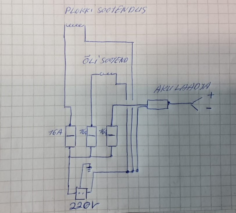
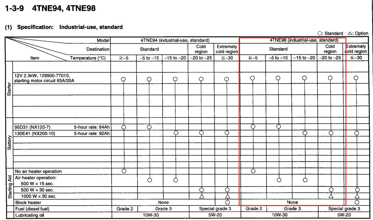
KINWONS CO.,LTD
Zhongren Building, No.300 Zhongcheng Road, Tianhe District, Guangzhou, China
Email: [email protected]
10-110V DC Work Light
Power Model Pics Specs
27W KS0027
10-110V
LED Power: 27W
Raw Lumen: 2160 LM
Operating Voltage: 10-110V DC
9pcs*3w high intensity Epistar LEDs
Color Temperature: 6000K
Material: Diecast aluminum housing
Lens material: PC
Mounting Bracket: Stainless Steel
Beam pattern: Spot/Flood
LED Life-Span: 30,000 hrs
Certificates: CE/UKCA/RoHS/IP68/ECE R10
Kinwons is one of expert in LED light bars/ LED driving lamps/ LED work lights/ LED
Interior lights/ LED warning lights
More about Kinwons please visit our website: www.kinwons.com
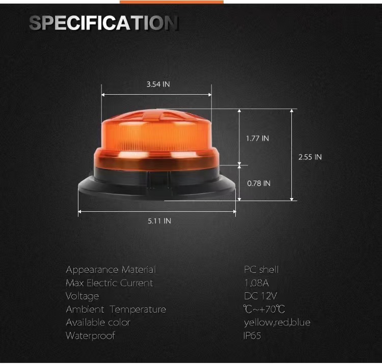
Goodsense FD25RTC4 hooldusplaan
1. aasta 2. aasta 3. aasta 4. aasta Mootoriõli Mootoriõli Mootoriõli Mootoriõli
Mootori õlifilter Mootori õlifilter Mootori õlifilter Mootori õlifilter
Õhufilter Õhufilter Õhufilter Õhufilter
Määrimis- ja kontrolltööd Määrimis- ja kontrolltööd Määrimis- ja kontrolltööd Määrimis- ja kontrolltööd
Kütusefilter Kütusefilter Kütusefilter Kütusefilter
Kütusepaagifilter Kütusepaagifilter Kütusepaagifilter Kütusepaagifilter
Käigukastifilter Käigukastifilter Käigukastifilter Käigukastifilter
Käigukastiõli Käigukastiõli Käigukastiõli Käigukastiõli
Piduriõli Piduriõli Piduriõli Piduriõli
Jahutusvedelik Jahutusvedelik Jahutusvedelik Jahutusvedelik
Sillaõli Sillaõli Sillaõli Sillaõli
Piduri peasilinder Piduri peasilinder
Kallutussilindri tihendid Kallutussilindri tihendid
Tõstesilindri tihendid Tõstesilindri tihendid
Hüdraulikafilter Hüdraulikafilter
Hüdroõli Hüdroõli
Kinnituskiri 13.04.2025
Käesolevaga kinnitame, et Goodsense FD25RTC4 maastikutõstuk:
- on võimeline töötama -20 °C kuni +30 °C temperatuurivahemikus (TK 1.2);
- on võimeline startima 50% kallakust üles maksimaalse koormaga (TK 2.1);
- on vajadusel võimeline töötama STANAG 7090 vastava F-63 kütusega ilma ümberehituseta.
Masinal ei ole AdBlue süsteemi ega heitgaaside järeltöötlussüsteemi (TK 2.3).
- on ehitatud selliselt, et elektrooniline konfiguratsioon töötab madala temperatuuriga kuni -20°C
(TK 2.5.4)
Karl Sarapuu
/allkirjastatud digitaalselt/
Global Technical Service Co., Ltd.
----------------------------------------------------------------------------------------------------------------------------------------------- Room 2103, 21/F Ho King Commercial Centre, No. 2-16 Fa Yuen Street, Mong kok, Kowloon ,HK.
TEST REPORT
EN ISO 3691-1
Industrial trucks — Safety requirements and verification — Part 1: Self-propelled industrial trucks, other than driverless trucks, variable-
reach trucks and burden-carrier trucks
Test report reference No. ................. : R90322222001-002
Tested by (+ signature) .................... : James Li
Approved by (+ signature) ................ : Kevin Zhang
Date of issue .................................... : 2022-11-07
Contents ........................................... : 37 pages
.......................................................... :
Client
Name ................................................ : Zhejiang Goodsense Forklift Co., Ltd.
Address ............................................ : Haichang Road 1188#, Binhai Industrial Zone, Taizhou, Zhejiang, China
Test specification
Standard ........................................... : EN ISO 3691-1:2015 + A1:2020
Test item
Description ....................................... : INTERNAL COMBUSTION Forklift Truck
Trademark ........................................ : None
Model and/or type reference ............ : FD15; FD18; FD20; FD25; FD30; FD35; FD40; FD45; FD50; FD60; FD70; FD80
Rating(s) ........................................... : Refer to instruction manual
Manufacturer .................................... : Zhejiang Goodsense Forklift Co., Ltd.
Haichang Road 1188#, Binhai Industrial Zone, Taizhou, Zhejiang,
China
page 2 of 37
Ref. No.: R90322222001-002
----------------------------------------------------------------------------------------------------------------------------------------------- Room 2103, 21/F Ho King Commercial Centre, No. 2-16 Fa Yuen Street, Mong kok, Kowloon ,HK.
Test case verdicts
Test case does not apply to the test object ............... : N(Not applicable)
Test item does meet the requirement ....................... : P(Pass)
Test item does not meet the requirement ................. : F(Fail)
Testing
Date of receipt of test item ....................................... : 2022-11-04
Date(s) of performance of test ................................... : 2022-11-04 - 2022-11-07
General remarks
This test report shall not be reproduced except in full without the written approval of the testing laboratory.
The test results presented in this report relate only to the item tested.
"(see remark #)" refers to a remark appended to the report.
"(see appended table)" refers to a table appended to the report.
Throughout this report a point is used as the point separator.
Test location: Taizhou, China
Type characteristics:
INTERNAL COMBUSTION Forklift Truck FD15; FD18; FD20; FD25; FD30; FD35; FD40; FD45; FD50; FD60; FD70; FD80
Detailed information refers to instruction manual.
Copy of marking plate: (as a sample)
page 3 of 37
Ref. No.: R90322222001-002
----------------------------------------------------------------------------------------------------------------------------------------------- Room 2103, 21/F Ho King Commercial Centre, No. 2-16 Fa Yuen Street, Mong kok, Kowloon ,HK.
EN ISO 3691-1:2015 + A1:2020
Clause Requirement - Test Result - Remark Verdict
4 Safety requirements and/or protective measures -
4.1 General -
4.1.1 Overall requirements
The truck shall comply with the safety requirements and/or protective measures of this clause.
See the remarks in the following clauses.
P
In addition, the truck shall be designed according to the principles of ISO 12100 for relevant but not significant hazards which are not dealt with by this document.
The hazards not covered by this standard are not significant and have been taken account according to EN ISO 12100:2010 during the stage of design.
P
4.1.2 Normal climatic conditions Refer to instruction manual
P
4.1.3 Normal operating conditions Refer to instruction manual
P
4.1.4 Electrical requirements -
Electrical requirements are subject to regional requirements. See ISO/TS 3691-7:2011 and ISO/TS 3691-8.
Complies with EN 1175:2020, see test report.
P
4.1.5 Edges or angles -
There shall be no sharp edges or angles posing a hazard in the area of the operator in the normal operating position and in the area of access and egress during normal operation and daily checks.
No sharp edges or angles posing a hazard.
P
4.1.6 Stored energy components -
Components which store energy and would cause a risk during removal or disassembly, e.g. Hydraulic accumulator or spring applied brakes, shall be provided with a means to release the energy before removal or disassembly.
No this kind of components on this truck.
N
4.2 Starting/Moving -
4.2.1 Unauthorised starting -
Trucks shall be provided with a device (e. g. a key, a code, a magnetic card) which prevents starting without that device.
Key is provided.
P
Devices for pedestrian controlled trucks and rider controlled trucks manufactured by the same manufacturer shall not be interchangeable between the two truck types.
The key between the trucks are not interchangeable.
P
page 4 of 37
Ref. No.: R90322222001-002
----------------------------------------------------------------------------------------------------------------------------------------------- Room 2103, 21/F Ho King Commercial Centre, No. 2-16 Fa Yuen Street, Mong kok, Kowloon ,HK.
EN ISO 3691-1:2015 + A1:2020
Clause Requirement - Test Result - Remark Verdict
Where devices, e.g. magnetic cards, are destined for an individual operator, one device may be used on both truck types but shall not allow starting by unauthorized persons.
No this kind of device on this truck.
N
4.2.2 Unintended movement and inadvertent activation -
Truck movement from the holding position, other than by actuation of the controls by the operator, due to drift or creep (e.g. by leakage), shall be avoided.
Movement due to drift or creep are avoided on this truck.
P
4.2.2.1 Parking brakes -
A parking brake shall be provided complying with 4.3.1.
See 4.3.1. P
For sit-down rider trucks the parking brake system should be manually operable by hand or foot from the normal operating position or automatically applied by leaving the normal operating position.
The parking brake is operated by hand from operating position.
P
Trucks, with only non-automatically applied parking brake(s), shall have a warning to the operator to apply brakes before leaving the truck.
The warning is provided. P
Failure of the control system of an automatically applied parking brake shall be indicated to the operator.
Not automatically parking brake.
N
4.2.2.2 Internal combustion engine powered trucks -
Internal combustion engine powered trucks shall be fitted with a device which prevents the engine being started while the transmission is engaged.
An automotive type manual gearbox and manually operated clutch pedal are provided.
P
4.2.2.3 Travel controls -
Travel controls on internal combustion engine powered trucks shall be so arranged that on level ground the truck will not move from rest until the transmission has been engaged.
The travel controls are so arranged.
P
4.2.2.4 Powered travel movement -
Powered travel movement of the truck with a ride on operator shall be possible only if the operator is in the normal operating position.
Seat switch is provided.
According to EN 1726-1, the parking brake and neutral travel control applied by the operator can satisfy this requirement.
P
page 5 of 37
Ref. No.: R90322222001-002
----------------------------------------------------------------------------------------------------------------------------------------------- Room 2103, 21/F Ho King Commercial Centre, No. 2-16 Fa Yuen Street, Mong kok, Kowloon ,HK.
EN ISO 3691-1:2015 + A1:2020
Clause Requirement - Test Result - Remark Verdict
Powered travel shall not occur automatically when the operator returns to the normal operating position without an additional operation, e.g. by requiring resetting the direction control or by reactivating speed control.
Reactivating speed control is required.
P
4.2.2.5 Manual gearbox and manually operated clutch pedal -
A truck with an automotive type manual gearbox and manually operated clutch pedal satisfies the requirements of 4.2.2.2 and 4.2.2.4.
An automotive type manual gearbox and manually operated clutch pedal are provided.
P
4.2.3 Travel speed -
4.2.3.1 Pedestrian controlled trucks Not such type truck -
Single speed pedestrian controlled trucks operating on level ground shall not exceed a travel speed of 4 km/h and acceleration of 0,5 m/s2 and shall be designed for low-lift only.
N
Variable speed pedestrian controlled trucks operating on level ground shall be controllable by the operator to align with their walking speed.
N
The maximum speed is subject to regional requirements. Additional to the requirements of this part of ISO 3691. See ISO/TS 3691-7:2011 and ISO/TS 3691-8.
N
4.2.3.2 Stand-on trucks and pedestrian controlled trucks with foldable platform
Not such type truck -
The maximum speed on level ground of stand-on trucks and pedestrian controlled trucks fitted with a foldable platform when the operator is on the platform is subject to regional requirements. Additional to the requirements of this part of ISO 3691. See ISO/TS 3691-7:2011 and ISO/TS 3691-8.
N
For trucks with a foldable operator platform, see 4.7.3.3.
N
For trucks with stand-on options, see 4.7.3.2 and 4.7.3.4.
N
4.2.3.3 Travel with mast raised This truck is not used for this situation.
-
Travel with mast raised is subject to additional regional requirements. See ISO TS 3691-8.
N
The speed of reach trucks shall be reduced automatically without causing a hazard to Vmax no more than 6 km/h as determined by the manufacturer when the elevated section of the mast is more than 400 mm above the height of the mast when fully lowered.
No reach trucks. N
4.3 Brakes -
4.3.1 General -
page 6 of 37
Ref. No.: R90322222001-002
----------------------------------------------------------------------------------------------------------------------------------------------- Room 2103, 21/F Ho King Commercial Centre, No. 2-16 Fa Yuen Street, Mong kok, Kowloon ,HK.
EN ISO 3691-1:2015 + A1:2020
Clause Requirement - Test Result - Remark Verdict
All industrial trucks shall be designed with service and parking brakes. Brakes shall comply with ISO 6292.
Service and parking brakes are designed complying with ISO 6292:2008.
P
The parking brake shall be equipped with a system preventing unintentional release.
The parking brake can not be released unintentionally.
P
The parking brake force shall be applied by mechanical means.
The parking brake force is applied by mechanical means.
P
Braking requirements are subject to regional requirements, additional to the requirements of this part of ISO 3691. See ISO/TS 3691-7:2011 and ISO/TS 3691-8.
The braking system maybe changed according to the country the truck used.
P
4.3.2 Failure of energy supply to automatically acting brakes -
Failure of the energy supply to the service brake shall not result in a total loss of braking and shall enable a controlled stop.
The service brake is hydraulic powered, when the supply fails, the truck can be stopped safely.
P
4.3.3 Stand-on and pedestrian controlled trucks -
Stand-on and pedestrian-controlled trucks shall be equipped with a brake system that will automatically engage upon release of the brake actuating control by the operator. This system may serve as the service and parking brake.
Not such type truck N
4.4 Manual control actuators -
4.4.1 General -
4.4.1.1 Consistency with the truck motions -
Movement of these controls shall be consistent with the motions of the truck being operated, wherever practicable. They shall be confined within the plan view outline of the truck or tiller.
The controls are consistent with the truck motions and are confined within the plan view outline of the truck.
P
4.4.1.2 Multiple operators -
If additional operating positions are fitted, e.g. for more than one operator, the operation of these controls shall only be possible from one operating position at a time, except the emergency disconnect switch, which shall be operable from all positions.
Only one operator on this truck.
N
4.4.1.3 Multiple operating positions -
If more than one operating position is fitted for a single operator, the use of the controls of one operating position shall preclude the use of the controls of other operating positions, except the emergency disconnect switch, which shall be operable from all positions.
Only one operating position on this truck.
N
4.4.2 Travel and braking controls -
page 7 of 37
Ref. No.: R90322222001-002
----------------------------------------------------------------------------------------------------------------------------------------------- Room 2103, 21/F Ho King Commercial Centre, No. 2-16 Fa Yuen Street, Mong kok, Kowloon ,HK.
EN ISO 3691-1:2015 + A1:2020
Clause Requirement - Test Result - Remark Verdict
4.4.2.1 General -
The motion of the speed operating control shall be designed in a way that an increase in the movement of the control increases the travel speed. When the control is released, it shall return to the neutral position of the control actuator.
The increase in the action of the speed pedal increases the travel speed. When the control is released, its action returns to neutral.
P
4.4.2.2 Sit-on trucks -
Trucks with pedal operated travel and braking controls shall comply with ISO 21281.
The travel and braking pedals comply with EN ISO 21281:2005.
P
4.4.2.3 Stand-on trucks Not such type truck -
The requirements for travel and braking controls for a stand-on truck are as follows.
-
a) Travel control function − Where a tiller is used it shall be fitted with control devices for travel direction and speed; − Where a steering wheel or similar control is used the controls for travel direction and speed shall be positioned in close proximity to the steering control.
N
The Service brake function shall be engaged: − automatically when the tiller is released if they are operated by the tiller; − automatically when the travel-control is released if they are operated by the travel-control; − automatically when releasing the pedal if the brake function is foot operated; − when activating the hand actuator if the brake function is hand operated.
N
b) On trucks with elevating operator platform of up to 1 200 mm means shall be provided to prevent travel, while the platform is elevated more than 500 mm unless the controls are elevated with the platform.
N
4.4.2.4 Pedestrian controlled trucks Not such type truck -
The requirements for pedestrian-controlled trucks are as follows.
-
a) The tiller shall be fitted with control devices for travel direction and speed.
N
b) When the tiller is released, it shall automatically return to its upper rest position, cut off traction power in the travel direction and engage the brake.
N
c) When the tiller is in its lowered position, the traction power in the travel direction shall be cut off and the brake shall be engaged.
N
d) The tiller shall be fitted with a device to energize the direction of travel away from the operator until pressure on the device is relieved, or that stops the truck by applying the brakes, if the head of the tiller in its operating position comes into contact with a solid body (e.g. the operator's body).
N
page 8 of 37
Ref. No.: R90322222001-002
----------------------------------------------------------------------------------------------------------------------------------------------- Room 2103, 21/F Ho King Commercial Centre, No. 2-16 Fa Yuen Street, Mong kok, Kowloon ,HK.
EN ISO 3691-1:2015 + A1:2020
Clause Requirement - Test Result - Remark Verdict
4.4.2.5 Differential locking No such device is designed for the trucks
-
It shall be possible to unlock the differential when the truck is moving.
N
For trucks fitted with a pedal-operated differential lock, depression of the pedal shall lock the differential and shall be released when releasing the pedal.
N
4.4.2.6 Additional operation from outside the truck This truck is not used for this situation.
-
If travel control from outside the truck is provided for the operator of sit-on or stand-on trucks and tractors, when operated from the outside the travel speed shall be limited to 6 km/h. These controls may be attached to the truck or a remote control may be provided, and the operating system shall be made operable by means of a separate switch or automatically when the operator leaves the normal operating position.
N
a) General 1) If the control actuator is released, the drive unit shall switch off automatically and the brake shall be engaged automatically. Simultaneous operation from the operating positions shall be excluded. 2) Controls fitted at the outside of the truck shall be secured against unintentional activation.
N
b) Additional requirements for cable-connected remote controls 1) The length and layout of the cables shall allow the operator to operate from outside of the area of hazard of the truck and have visibility of the path of travel. It shall not be possible for the cable to become entangled with the wheels. 2) On a portable control panel, the control elements, with the exception of the emergency stop, shall be guarded against unintentional operation. The portable control panel shall be fitted with an emergency stop device in accordance with ISO 13850.
N
page 9 of 37
Ref. No.: R90322222001-002
----------------------------------------------------------------------------------------------------------------------------------------------- Room 2103, 21/F Ho King Commercial Centre, No. 2-16 Fa Yuen Street, Mong kok, Kowloon ,HK.
EN ISO 3691-1:2015 + A1:2020
Clause Requirement - Test Result - Remark Verdict
c) Additional requirements for cableless control 1) The transmission range shall be adequate to allow the operator to operate from outside the area of hazards of the truck and have visibility in the path of travel. 2) On the portable control panel, the control elements for operation, with the exception of the emergency stop, shall be guarded against unintentional operation. 3) The reliability level shall be at least 10 9 and the Hamming distance shall be 2. The remote control shall be in accordance with ISO 13849-1, performance level (PL) c. 4) The truck shall stop automatically when outside of the operator's direct view (90°) and/or out of range of the remote control. 5) No control interference shall be possible when more than one truck is operating under remote control at the same time.
N
d) Additional requirements for trucks with trailer coupling 1) The controls (e.g. rear touch device) shall be arranged so that the operator does not have to step between the truck and the trailer in order to operate them. 2) The rear touch device shall be secured against unintentional operation. 3) During operation of the rear touch device, the travel speed of the truck shall not exceed 2,5 km/h.
N
4.4.2.7 Additional operation from alongside pedestrian- controlled and stand-on trucks (coasting)
Not this kind of truck. -
The additional operation of pedestrian-controlled and stand-on trucks while the operator is walking alongside the truck shall only be possible with the truck's fork arms trailing.
N
The additional operation of such trucks while the operator is walking alongside the truck, and the use of low-lift order-picking trucks provided with a system that allows for operation while walking alongside the truck, are subject to regional requirements, additional to the requirements of this part of ISO 3691. See ISO/TS 3691-7:2011 and ISO/TS 3691-8.
N
4.4.3 Steering controls -
4.4.3.1 Steering direction -
The following applies.
a) For stand-on or sit-on trucks, when travelling in the forward direction, clockwise rotation of the steering wheel, or equivalent movement of the steering control, shall steer the truck to the right;
The clockwise rotation of the steering wheel steers the truck to the right when driving forwards.
P
page 10 of 37
Ref. No.: R90322222001-002
----------------------------------------------------------------------------------------------------------------------------------------------- Room 2103, 21/F Ho King Commercial Centre, No. 2-16 Fa Yuen Street, Mong kok, Kowloon ,HK.
EN ISO 3691-1:2015 + A1:2020
Clause Requirement - Test Result - Remark Verdict
b) For trucks with an operator control position rotatable by more than 90°, or having duplicated control positions, in order to facilitate the operator facing in the opposite direction, clockwise rotation of the steering wheel, or equivalent movement of the steering control, shall steer the truck to the right as viewed from the new position — i.e. the steering control sense is reversed beyond 90° to facilitate the operator facing in the opposite direction.
No rotating operator seat or duplicated control positions are provided for three trucks
N
c) Trucks with continuous 360° steering, i.e., the steering/drive wheel can move through 360° to propel the truck in the direction selected by the steering control, shall operate in the same sense as a) when travelling in the forward direction;
Not this kind of truck. N
d) For pedestrian operated trucks fitted with a tiller, when travelling in the forward direction, clockwise movement of the tiller shall steer the truck to the right;
Not this kind of truck. N
e) Exceptionally, when requested by the user, end- control trucks may be equipped with “reverse steering” — i.e. clockwise rotation of the steering control will steer the truck to the left. Such trucks should be clearly identified.
Not this kind of truck. N
4.4.3.2 Failure of power supply -
In the event of an interruption of the power supplied to the steering system (including a dead motor or engine) it shall be possible to maintain the path being steered until the truck is brought to a controlled stop.
When the power fails, the path being steered can be maintained.
P
4.4.4 Load handling controls -
4.4.4.1 Controls -
Controls shall return to the neutral position when released and stop the corresponding load movement.
The control for loading is always return to neutral, unless it is under the intended operation of operator
P
When single levers are used to control a function on trucks other than reach trucks with retractable mast or forks, the lever closest to the operator shall control lifting and lowering, the second closest lever should control the tilt function, the third closest lever should control the side shift and the fourth closest lever should be for auxiliary functions.
The levers on this truck are so arranged.
P
When single levers are used to control a function on reach trucks with a retractable mast or forks, the lever closest to the operator shall control lifting and lowering, the second closest lever should control the displacement of the mast or forks, the third closest lever should control the tilt function, the fourth closest lever should control side shift and the fifth closest lever should be for auxiliary functions.
Not this kind of truck. N
page 11 of 37
Ref. No.: R90322222001-002
----------------------------------------------------------------------------------------------------------------------------------------------- Room 2103, 21/F Ho King Commercial Centre, No. 2-16 Fa Yuen Street, Mong kok, Kowloon ,HK.
EN ISO 3691-1:2015 + A1:2020
Clause Requirement - Test Result - Remark Verdict
Trucks equipped with attachments which hold the load by power (e.g. paper clamp) shall feature control(s) with a secondary action to prevent unintentional release of the load.
No attachments on this truck.
N
4.4.4.2 Manual lift systems No such lift system -
The hand power forces and the layout of controls of manually operated lifting systems shall comply with ISO/DIS 3691-5.
N
4.4.5 Multi-function controls No such controls -
Where a control is designed and constructed to perform more than one function, each separate function shall be clearly marked. Each control function shall return to the neutral position when released and stop the corresponding load movement.
N
4.4.6 Controls for automated functions No such controls -
The controls for automated functions shall comply with ISO 24134.
N
4.4.7 Marking -
Graphic symbols used for marking controls shall comply with 6.3.1.4.
See clause 6.3.1.4. P
4.5 Power systems and accessories -
4.5.1 Exhaust and cooling systems -
4.5.1.1 Exhaust system -
The exhaust system shall be designed in accordance with 4.7.6 and such that engine exhaust is directed away from the operator position.
The engine exhaust is directed away from the operator position and designed according to 4.7.6.
P
Materials used in the vicinity of exhaust systems shall be non-flammable and shall be chosen and protected such that they are not adversely affected by heat from the exhaust system.
The materials are non- flammable and protected appropriately.
P
4.5.1.2 Cooling system -
The air flow through the cooling system shall be arranged in a manner to avoid discomfort to the operator.
No cooling system for the operator on this truck.
N
4.5.2 Fuel tank -
4.5.2.1 Tank isolation -
If a fuel tank is within or adjacent to the engine compartment and excessively high temperatures can occur, the tank and/or filling arrangement shall be isolated from the electrical and exhaust systems by suitable protection, e.g. a separate enclosure or baffles.
The fuel tank is far from the engine compartment and no high temperature can occur.
N
page 12 of 37
Ref. No.: R90322222001-002
----------------------------------------------------------------------------------------------------------------------------------------------- Room 2103, 21/F Ho King Commercial Centre, No. 2-16 Fa Yuen Street, Mong kok, Kowloon ,HK.
EN ISO 3691-1:2015 + A1:2020
Clause Requirement - Test Result - Remark Verdict
The tank location and facilities for filling shall be such that spillage or leakage will not drain into the engine or operator's compartment or onto electrical or exhaust system parts.
The spillage or leakage will not affect these components.
P
4.5.2.2 Fuel spillage -
Fuel spillage shall not be possible under normal operating conditions.
No fuel spillage under normal conditions.
P
4.5.3 Access to engine and other compartments -
4.5.3.1 Engine cover -
An enclosed engine compartment shall satisfy fan guarding requirements when the manufacturer's recommended routine maintenance is performed with the engine off. If a fan can start (e.g. temperature switch) when the engine is off, the fan shall be guarded. A safety warning sign shall be provided, and included in the instruction handbook (see 6.2). Warnings shall comply with 6.3.3.4.
The engine is in an enclosed compartment with cover. The fan is guarded and warning sign is provided.
P
Access from underneath is considered guarded if the access ground clearance is less than 600 mm between the underside of the truck and level ground.
No access underneath is provided.
N
4.5.3.2 Unintentional closure -
Where unintentional closure could cause injury, access covers (i.e. traction battery or engine covers) shall be provided with means for preventing unintentional closure. Those means shall be permanently affixed to the truck or stored in a safe place on the truck.
A supporting bar is provided to support when the engine cover is opened.
P
4.5.4 Liquefied petroleum gas (LPG)-powered trucks Not this kind of truck. -
4.6 Systems for lifting and tilting -
4.6.1 Lift chains -
The truck or mast manufacturer shall have on record a certificate from the chain manufacturer giving the breaking load of the chains used.
Refer to test reports of chains.
P
When the lifting mechanism includes a chain or chains, the truck manufacturer shall only use leaf or roller chains.
Leaf chains are used on this truck.
P
page 13 of 37
Ref. No.: R90322222001-002
----------------------------------------------------------------------------------------------------------------------------------------------- Room 2103, 21/F Ho King Commercial Centre, No. 2-16 Fa Yuen Street, Mong kok, Kowloon ,HK.
EN ISO 3691-1:2015 + A1:2020
Clause Requirement - Test Result - Remark Verdict
These shall provide a minimum factor, K1, when supporting the maximum capacity load and assuming no friction in the mast structure, which is given by the following equation:
See the calculation notes.
P
Pulley diameters shall be in accordance with the chain manufacturer's instructions.
Pulley diameters are more than three times the pitch of the chains.
P
4.6.2 Mechanical lifting system No such system. -
4.6.2.1 General -
The lifting system shall comply with the requirements of 4.6.3.3.
N
4.6.2.2 Failure of lifting/lowering mechanism -
In the event of failure of the lifting/lowering mechanism or its parts (e.g. gearwheel, chainwheel, or spindle,) it shall not cause the elevated load or operator’s platform to fall.
N
4.6.2.3 Lowering speed -
The lowering speed of the lifting mechanism with its rated load shall not exceed 0, 6 m/s.
N
4.6.3 Hydraulic lifting and tilting system -
4.6.3.1 Hydraulic lifting system -
The hydraulic lifting system shall be designed in a way that, with the hydraulic fluid at normal operating temperature, the mast substantially vertical and carrying rated capacity load, the descent of the load caused by internal leakage in the first 10 minutes shall not exceed: 100 mm for trucks up to and including 10 000 kg rated capacity. 200 mm for trucks over 10 000 kg rated capacity.
5 mm tested during the first 10 min.
P
4.6.3.2 Lowering speed limitation -
A device shall be incorporated in the lift circuit which, in the event of a failure of the hydraulic circuit — excluding the hydraulic lift cylinder(s) — shall restrict the rate of descent of the lifting mechanism with its rated load to 0,6 m/s maximum. The device shall be fitted directly at the lifting cylinder(s).
Tested 0,2 m/s. P
4.6.3.3 Limitation of stroke -
The lift assembly shall be fitted with a positive means to prevent over-travel. In addition, positive means (e.g. mechanical stop) shall be provided to prevent the fork carrier and moving elements of the mast structure from unintentionally disengaging from the upper end of the mast.
Two over travel blocks are provide.
P
4.6.3.4 Hydraulic tilting systems -
page 14 of 37
Ref. No.: R90322222001-002
----------------------------------------------------------------------------------------------------------------------------------------------- Room 2103, 21/F Ho King Commercial Centre, No. 2-16 Fa Yuen Street, Mong kok, Kowloon ,HK.
EN ISO 3691-1:2015 + A1:2020
Clause Requirement - Test Result - Remark Verdict
The internal leakage rate of the complete hydraulic tilting system (i.e. cylinder, valve, etc.) with the oil at normal operating temperature shall allow no more than 5° forward movement of the mast in 10 minutes from the vertical mast position when the rated load is at a height of 2 500 mm or, in the case of trucks with lift heights of less than 2 500 mm, at their maximum lift height. The average tilting speed allowed by internal leaks shall not exceed 0, 5°/min for trucks with a maximum forward tilt of less than 5°.
2°tested during the first 10 min.
The average tilting speed is 0.2°/min.
P
4.6.3.5 Mast tilt and carriage isolation -
For ride-on trucks, mast tilt and carriage movement shall not be possible through operation of the primary load-handling control when the operator is not in the normal operating position.
The control and speed pedal need to be operated at the same time for these operating.
P
Isolation of attachment movement is subject to regional requirements, additional to the requirements of this part of ISO 3691. See ISO/TS 3691-7:2011.
No attachment on this truck.
N
4.6.4 Hydraulic system -
4.6.4.1 Hydraulic circuit -
Hoses, piping and connections subjected to internal pressure shall be capable of withstanding, without bursting or permanent deformation, a pressure equal to at least three times the operating pressure.
See the test reports of these components.
P
Pipes and hoses shall be located and, if necessary, restrained, so that deterioration, sharp edges and other damage-causing sources are minimized.
These hazards are avoided on this truck for pipes and hoses.
P
4.6.4.2 Pressure controls -
All hydraulic systems shall include a device which prevents the pressure in the system from exceeding a preset level. The device shall be so designed and fitted that unintentional loosening or adjustment is avoided and so that a tool or key is required to alter the pressure setting.
The pressure limitation valve is provided and which is set by manufacture, any adjustment is only can be done by broken the lead sealing.
P
4.6.4.3 Failure of energy supply to hydraulic circuit
In the case of a fault or interruption of the supply of energy, the design of the hydraulic system shall be such that it does not allow any uncontrolled motion of equipment or attachment.
The pump can not work as a hydraulic motor in case of a fault or interruption of the supply of energy
P
4.6.4.4 Fluid purification -
The hydraulic system(s) shall be protected against the risk of contamination of the hydraulic fluid e.g. by means of magnet(s), filter(s).
Hydraulic oil filter is provided.
P
4.6.5 Load handling and stacking attachments No attachments on this truck.
-
page 15 of 37
Ref. No.: R90322222001-002
----------------------------------------------------------------------------------------------------------------------------------------------- Room 2103, 21/F Ho King Commercial Centre, No. 2-16 Fa Yuen Street, Mong kok, Kowloon ,HK.
EN ISO 3691-1:2015 + A1:2020
Clause Requirement - Test Result - Remark Verdict
4.6.5.1 Unintentional displacement or detachment -
Means shall be provided to prevent the unintentional lateral displacement or unintentional detachment of attachments from the truck.
N
Movement of the attachment and its parts shall be mechanically limited at the extreme positions.
N
4.6.5.2 Malfunction in the power supply system -
Attachments, which hold the load by power, shall be designed in such a way that the maximum load they are intended to handle is automatically retained for at least 10 minutes when the truck's manual controls are in the neutral position or in the event of a malfunction in the power supply system for the attachment.
N
4.6.5.3 Hydraulic system for attachment -
If an attachment has its own separate hydraulic system, it shall comply with 4.6.4.
N
4.6.5.4 Combined hydraulic systems -
If an attachment has a hydraulic system which is connected to the truck hydraulic system, the two systems shall be compatible and the combined systems shall comply with 4.6.4.
N
4.6.5.5 Attachment for lifting freight containers -
An attachment for lifting freight containers shall be equipped with indicator lights according to ISO 15871. The attachment shall have a device(s) to prevent unintentional dropping of a container. Means shall be provided to prevent lifting of the container unless all interface mechanisms are fully engaged and locked. If multiple containers are lifted at the same time, the same requirements are valid for all containers. Travel speed shall be restricted to a maximum of 10 km/h if the container is not locked to the attachment in a manner that will prevent unintentional drop (e.g. lifting with grapple arms).
N
4.6.5.6 Fork arms -
4.6.5.6.1
Solid-section fork arms shall be manufactured and tested in accordance with ISO 2330, except with respect to safety factors. The safety factors are subject to regional requirements, additional to the requirements of this part of ISO 3691. See ISO/TS 3691-8.
See the test report of fork arms.
P
4.6.5.6.2 The total capacity of all fork arms fitted to a truck shall not be less than the actual capacity of the truck.
See the test report of fork arms.
P
4.6.5.6.3 Means shall be provided to prevent unintentional lateral displacement of the fork arms on the fork carrier.
The dismounting block is provided on the fork carrier.
P
4.6.5.6.4 Fork-arm extensions shall be designed to prevent accidental disengagement from the fork arms, and shall be in accordance with ISO 13284.
No fork-arm extensions on this truck.
N
page 16 of 37
Ref. No.: R90322222001-002
----------------------------------------------------------------------------------------------------------------------------------------------- Room 2103, 21/F Ho King Commercial Centre, No. 2-16 Fa Yuen Street, Mong kok, Kowloon ,HK.
EN ISO 3691-1:2015 + A1:2020
Clause Requirement - Test Result - Remark Verdict
4.6.5.7 Fork carriers -
Hook-on type fork carriers shall be in accordance with ISO 2328.
The fork carrier is in accordance with ISO 2328:2007.
P
4.7 Operator position -
4.7.1 Dimensions -
The operator's seat or standing position shall be so located that the operator has sufficient room while operating the truck so as to remain within the plan view outline of the truck. The dimensions shall be of suitable and ergonomic shape to accommodate at least a 5th percentile to a 95th percentile of the population, as shown in ISO 3411:2007, Figures 1 to 3, within the plan view outline of the truck. The seat shall not extend beyond the plan view outline of the truck.
The operator has enough room which is greater than the dimensions showed in the Figures. See the drawings of the operator position.
P
The minimum distance from the top edge of the seat back to the plan view outline shall be 50 mm (see Figures 1 and 2).
The distance is 200 mm. P
For stand-on pedestrian- and centre-controlled ride-on trucks employing a tiller, the tiller steering control movement may extend beyond the plan view.
No tiller on this truck. N
4.7.2 Operator access and egress -
4.7.2.1 General -
Trucks shall be designed to permit safe and easy access and egress and to minimize the risk of slipping, falling and tripping. Steps, running boards and hand holds (grab handles, fixed parts of the truck structure, etc.) shall be provided above a step height of 350 mm to give three-point contact at all heights (i.e. one hand and two feet or two hands and one foot). Step width, instep clearance and toe clearance shall comply with ISO 2867.
See the drawing of access and the following clauses.
P
4.7.2.2 Steps -
page 17 of 37
Ref. No.: R90322222001-002
----------------------------------------------------------------------------------------------------------------------------------------------- Room 2103, 21/F Ho King Commercial Centre, No. 2-16 Fa Yuen Street, Mong kok, Kowloon ,HK.
EN ISO 3691-1:2015 + A1:2020
Clause Requirement - Test Result - Remark Verdict
Steps shall have slip-resistant surfaces or covering (e.g. expanded metal, abrasive coating). The first step shall be not more than 550 mm from the ground and succeeding steps shall be 250 mm to 350 mm, preferably at equal intervals.
For FD10/15/18
Two steps are provided.
The first step height from ground is 300 mm, the second one is 200 mm. step width complies with ISO 2867:2011. See the drawings for the access.
For FD20/25/30/35
Two steps are provided.
The first step height from ground is 475 mm, the second one is 200 mm. step width complies with ISO 2867:2011. See the drawings for the access
For FD/40/45/50
Three steps are provided.
The first step height from ground is 340 mm, the second one is 315 mm, the third one is 280 mm. step width complies with ISO 2867:2011. See the drawings for the access.
For FD50/60/70/80
Three steps are provided.
The first step height from ground is 445 mm, the second one is 270 mm, the third one is 270 mm. step width complies with ISO 2867:2011. See the drawings for the access.
P
4.7.2.3 Compartment floor -
The compartment floor frequented by the operator, steps and walkways shall have a slip resistant surface, e.g. ribbed mats, abrasive coating, expanded metal.
Ribbed mats surface are provided for such areas.
P
4.7.2.4 Walkways No such construction -
page 18 of 37
Ref. No.: R90322222001-002
----------------------------------------------------------------------------------------------------------------------------------------------- Room 2103, 21/F Ho King Commercial Centre, No. 2-16 Fa Yuen Street, Mong kok, Kowloon ,HK.
EN ISO 3691-1:2015 + A1:2020
Clause Requirement - Test Result - Remark Verdict
Walkways more than 2 000 mm from the ground shall have guard rails. The guard rails have a height of 1 000 mm to 1 100 mm and shall be capable of withstanding, without permanent deformation, a force of 900 N applied in a horizontal direction from inside to outside.
N
4.7.2.5 Hand holds -
For access to, and egress from, the normal operating position with a floor height above 300 mm, hand hold(s) shall be provided; these may be part of the truck structure. The clearance dimension for a hand hold shall be at least of 45 mm width, 130 mm length and diameter of 15 mm (see Figure 3).
Hand-hold is provided.
The width is 80 mm, length is 260mm or 280 mm, diameter is 22 mm.
P
4.7.3 Platform No such construction -
4.7.3.1 General -
Operator's stand-on platforms on pedestrian and stand-on end-controlled trucks shall be dimensioned in accordance with 5.7.1 and be capable of withstanding a compression force corresponding to 2,5 times the mass of the laden truck applied along the longitudinal axis of the truck with the outermost projection of the platform against a flat vertical surface. For the purpose of this requirement, the operator's platform includes any surrounding reinforcement or parts of the truck which provide resistance to crushing of the platform except for pedestrian controlled stand on trucks employing a tiller.
N
4.7.3.2 Platforms overhanging the truck chassis -
Platforms overhanging the truck chassis on tiller operated stand-on trucks, capable of travelling more than 6 km/h, shall, in addition to 5.7.3.1, be provided with a guard at either the sides or the front of the platform. The guards shall be capable of withstanding a horizontal force of 900N acting from inside to outside applied in line with the centre of the operator's standing position without permanent deflection. The side guards shall be at a minimum height of 700 mm above the platform in its protective position. Travelling more than 6km/h shall only be possible when the platform is pivoted down and guards are in their protective position.
N
4.7.3.3 Pedestrian controlled trucks with foldable platform -
page 19 of 37
Ref. No.: R90322222001-002
----------------------------------------------------------------------------------------------------------------------------------------------- Room 2103, 21/F Ho King Commercial Centre, No. 2-16 Fa Yuen Street, Mong kok, Kowloon ,HK.
EN ISO 3691-1:2015 + A1:2020
Clause Requirement - Test Result - Remark Verdict
Operator's stand-on platforms, which are fitted to pedestrian controlled trucks and overhang the truck's chassis may be capable of being folded or pivoted to an upright position when the operator leaves the platform, this may be done automatically.
N
For platforms which do not act automatically, devices shall be provided to prevent the truck manoeuvring or travelling unless the operator is standing on the platform or the platform is in its upper rest position.
N
4.7.3.4 Stand-on platforms -
Operators stand-on platforms which are built within the plan view outline of pedestrian controlled trucks where the operator stands to the side of the motor housing, shall be equipped with an additional grab rail for operator stability when riding. This grab rail shall be capable of withstanding a horizontal force of 900 N applied in line with the operator’s standing position, without permanent deformation. For this configuration of pedestrian controlled trucks the requirements of 5.7.3.2 do not apply.
N
4.7.3.5 Fixed operator’s stand-on platforms -
Fixed operator's stand-on platforms located at heights more than 1 200 mm shall be equipped with guard rails or other equally effective means of protection on all sides. Where guard rails are fitted they shall comprise top rails, intermediate rails, and toe boards to a height of not less than 900 mm or more than 1 100 mm measured from the upper surface of the top rail to the platform, the toe boards having a minimum height of 100 mm. The means shall be capable of withstanding without permanent deformation a force of 900 N applied in a vertical downwards direction and in a horizontal direction from inside to outside and shall not be capable of opening outwards.
N
4.7.3.6 Trucks with foldable platforms and foldable side guards
-
On trucks with side guards and platforms of the folding or pivoting type as described in 5.7.3.2 and 5.7.3.5, travelling movement shall only be possible when the side guard or platform is in a protective position or an inactive rest position. No travelling movement is allowed with the platform or side guard in an intermediate position.
N
4.7.4 Operator's seat -
The seat shall be designed and located to provide easy access to the controls, shall provide a position for the truck operator in accordance with ergonomic principles and shall meet the following requirements.
Can provide ready access to the controls and comfortable position.
P
a) If the seat has a facility allowing fore and aft adjustment this shall be possible without using tools;
It can be adjusted by manual
P
page 20 of 37
Ref. No.: R90322222001-002
----------------------------------------------------------------------------------------------------------------------------------------------- Room 2103, 21/F Ho King Commercial Centre, No. 2-16 Fa Yuen Street, Mong kok, Kowloon ,HK.
EN ISO 3691-1:2015 + A1:2020
Clause Requirement - Test Result - Remark Verdict
b) If a weight adjustable seat is fitted to reduce vibration transmitted to the operator, the adjustment shall accommodate operator weights of 55 kg to 110 kg. Manual adjustment of the weight mechanism shall be possible without using tools;
The seat is not weight- adjustable type.
N
c) If a seat has a facility allowing it to swivel about a vertical axis, this shall be possible at all seat adjustment positions without unintentional operation of controls;
Not such type seat. N
d) The seat mounting shall withstand the forces which may occur during operation e. g. braking forces, as well as the forces brought by the operator restraint defined in 4.7.8;
The mounting construction has enough mechanical strength
P
e) The requirements of a) to d) also apply to additional operator’s seats;
No additional operator’s seat.
N
f) When using an auxiliary seat on a stand-on industrial truck a padded seat surface and backrest is sufficient. If the operating space of the stand-on operator is restricted, the auxiliary seat shall be capable of being folded or pivoted.
Not stand-on truck. N
g) The seat anchorage to the battery cover or engine cover of sit-on counterbalanced trucks, as well as the latching method of the cover to the truck chassis, shall have sufficient strength in the event of a backwards tip-over of the truck from a loading dock. The seat anchorage shall be able to withstand a force of 2 250 N at a 45°+-5°angle, as shown in Figure 4.
During the test, the seat anchorage is able to withstand this force.
P
4.7.5 Protection from road wheels and objects thrown up by the wheels
-
4.7.5.1 Ride-on trucks -
In the normal operating position, the operator shall be protected against contact with the truck wheels and against objects thrown up by the wheels (e.g. mud, gravel, debris). The protection device for the steered wheels need only cover the wheels when in a straight- line position.
All wheels are guarded properly
P
4.7.5.2 Pedestrian controlled trucks Not such type truck -
The operator in the normal operating position shall be protected against contact with the drive and stabilizing wheels. The position of these wheel protections shall be in accordance with Figure 5.
N
4.7.6 Protection from burning -
page 21 of 37
Ref. No.: R90322222001-002
----------------------------------------------------------------------------------------------------------------------------------------------- Room 2103, 21/F Ho King Commercial Centre, No. 2-16 Fa Yuen Street, Mong kok, Kowloon ,HK.
EN ISO 3691-1:2015 + A1:2020
Clause Requirement - Test Result - Remark Verdict
All parts of the truck within reach of the operator in the normal operating position or when getting into or leaving their operating position shall be insulated or shielded so that the surface temperature, generated by heat sources in the truck, of bare meta painted or plastic parts 83 °C. The temperature of the air at the heater outlet, where fitted, shall not exceed 60 °C.
All such surfaces are insulated or shielded so that no accessible surface temperature can exceed 60 0C.
P
4.7.7 Protection against crushing, shearing and trapping -
4.7.7.1 General -
Parts which move relative to one another and are within reach of the operator in the normal operating position shall be adequately guarded. If hazards still exist, those shall be identified in 6.2 and, if possible, on the truck in accordance with 6.3.3.4.
No such dangerous situation for any normal operation.
P
Fixed guards and their mounting systems and fixed and/or removable guard systems are subject to regional requirements, additional to the requirements of this part of ISO 3691. See ISO/TS 3691-7:2011.
Regional requirements are taken into account.
P
4.7.7.2 Minimum distances -
Parts separated by the following minimum distance shall satisfy the adequately guarded requirements of 5.7.7.1: a) Places where only the operators fingers can be trapped: min 25 mm; b) Places where only the operators hands or feet can be trapped: min 50 mm; c) Places where the operators arms or legs can be trapped: min 100 mm.
No such dangerous situation for any normal operation.
P
Moving parts that need to be in contact with, or move in close proximity to, one another shall be guarded. Any openings in such guarding shall be small enough to prevent an 8 mm diameter probe from passing through them. If such hazards still exist, they shall be identified on the truck in accordance with 6.3.3.4.
No such parts on the truck.
N
4.7.7.3 Attachments No attachments -
Crushing and shearing hazards to the operator in the normal operating position associated with attachments, except at the load supporting points, shall also meet the relevant requirements of 4.7.7.1. If such hazards still exist, they shall be identified according to 6.2 and on the attachment by a warning sign in accordance with 6.3.3.4.
N
4.7.7.4 Foot protection -
Trucks with a side-facing seated or standing operator shall be so built that when travelling, the operator cannot unintentionally place his feet outside the confines of the truck; or, alternatively, the truck shall be equipped with a traction cut off (e.g. dead-man switch), enabled whenever an operator's foot is not in the safeguarded position.
Not this kind of truck. N
page 22 of 37
Ref. No.: R90322222001-002
----------------------------------------------------------------------------------------------------------------------------------------------- Room 2103, 21/F Ho King Commercial Centre, No. 2-16 Fa Yuen Street, Mong kok, Kowloon ,HK.
EN ISO 3691-1:2015 + A1:2020
Clause Requirement - Test Result - Remark Verdict
4.7.8 Operator restraint -
Sit-on counterbalanced lift trucks with a rated capacity up to and including 10 000 kg and sit-on, single side-loading trucks shall have a restraint device, system or enclosure intended to reduce the risk of entrapment of the operator's head and/or torso between the truck and the ground in the event of a tip- over.
The seat belt is provided; refer to test report of seat belt.
P
Such means shall not unduly restrict the operation of the truck, e.g. the operator's access, egress, and/or visibility. Warnings and instructions on the purpose, use and action to be taken in the event of a tip-over, so as to reduce the risk associated with the operator's head impacting a solid surface, shall be provided on the truck and described in the instruction handbook (see 6.2).
The seat belt does not unduly restrict the operation.
The seat is anchored in frame reliably and the seat belt is used. There is description how to do in the event of a tip over in the instruction manual.
P
If a restraint system with a belt is used, this system shall be in accordance with ISO 24135-1.
See the test report of seat belt.
P
Operator restraint requirements for sit-on counterbalanced trucks are subject to regional requirements, additional to the requirements of this part of ISO 3691, including requirements for counterbalanced lift trucks having a centre control, sit- on, non-elevating operator and a rated capacity up to and including 10 000 kg, and sit-on, single side- loading trucks. See ISO/TS 3691-8.
Regional requirements are taken into account.
P
4.7.9 Additional operator positions -
Additional operator position(s) shall comply with the requirements as specified in 4.7.1 through 4.7.8.
No additional operator position.
N
4.8 Stability The test is performed and passed.
P
4.9 Protective devices -
4.9.1 Overhead guard -
4.9.1.1 General -
Ride-on trucks with a maximum lift height more than 1 800 mm above the floor shall be fitted with an overhead guard complying with ISO 6055 to protect the operator from falling objects.
Overhead guard is tested and complies with ISO 6055:2004.
P
Trucks with an elevating operator position up to and including 1 200 mm that feature a lift height of the load of more than 1 800 mm above the operator platform shall be fitted with an overhead guard complying with ISO 6055 to protect the operator from falling objects.
Not this kind of truck. N
4.9.1.2 Additional fitting against falling small objects -
page 23 of 37
Ref. No.: R90322222001-002
----------------------------------------------------------------------------------------------------------------------------------------------- Room 2103, 21/F Ho King Commercial Centre, No. 2-16 Fa Yuen Street, Mong kok, Kowloon ,HK.
EN ISO 3691-1:2015 + A1:2020
Clause Requirement - Test Result - Remark Verdict
The overhead guard specified in 4.9.1.1 shall, when handling a load above 1 800 mm lift height, be constructed in such a manner that it can be provided with an additional fitting making it possible in those special cases to increase the protection of the operator against falling small objects.
The opening on the guard can protect from small falling objects.
P
4.9.1.3 Pedestrian controlled trucks with foldable platform -
Pedestrian-controlled trucks with a foldable platform as specified in 4.7.3.3 shall be provided with means to prevent lifting over 1 800 mm from the floor when the side guards are in their protective position. This does not apply if an overhead guard as specified in 4.9.1.1 is fitted on the truck.
Not this kind of truck. N
4.9.2 Load backrest extension -
4.9.2.1 Provision for load backrest extension -
Trucks fitted with fork arms with a lift height of more than 1 800 mm shall be designed so that they can be fitted with a load backrest extension.
The load backrest extension is provided.
P
4.9.2.2 Size of openings -
Load backrest extensions, if provided, shall have height, width, and size openings sufficient to minimize the possibility of the load falling toward the mast when the mast is in a position of maximum rearward tilt.
The dimensions of the load backrest extension are enough.
P
The size of openings in the load backrest extension, if provided, shall not exceed 150 mm in one of the two dimensions.
The max. dimension of the opening is:
- FD50/60/70/80: 150 mm
- FD30/35/40/45/50: 133 mm
- FD20/25: 144 mm
- FD10/15/18: 134 mm
P
4.9.3 Warning device -
Trucks shall be equipped with an operator controlled audible warning device.
The horn is provided.
P
4.9.4 Wheels with split wheel rims for inflatable tyres -
page 24 of 37
Ref. No.: R90322222001-002
----------------------------------------------------------------------------------------------------------------------------------------------- Room 2103, 21/F Ho King Commercial Centre, No. 2-16 Fa Yuen Street, Mong kok, Kowloon ,HK.
EN ISO 3691-1:2015 + A1:2020
Clause Requirement - Test Result - Remark Verdict
When split wheel rims are used with pneumatic tyres, the truck shall be provided with means to prevent the user from separating the halves of the wheel before removing it from the axle. Information on the proper means of removing the tyre from the wheel shall be provided in the instruction handbook (see 6.2).
Cage protector is provided to prevent this situation.
P
4.9.5 Traction battery compartment No traction battery. -
4.9.5.1
Unauthorized access -
On trucks with a nominal battery voltage exceeding 120 V d.c., if a lockable cover is not present on the battery enclosure, facilities shall be provided to enable the battery compartment to be secured so as to prevent unauthorized access to the battery.
N
4.9.5.2 Metal cover -
A metal cover for a battery compartment or battery enclosure shall have either
N
a) sufficient strength and rigidity, in conjunction with an air spacing of at least 30 mm provided between it and the battery terminals, so that the battery terminals are not short-circuited when a 980 N force is applied
to any area 300 mm 300 mm of the cover, or
N
b) an air space reduced to a minimum of 10 mm, provided covers or live parts of the battery are insulated in such a way that disintegration and/or displacement of the insulation is prevented.
N
4.9.5.3 Non-metallic cover -
For non-metallic covers of battery compartments, the following applies.
N
a) The cover shall have a burn rating of V0 or V1 in accordance with IEC 60695-11-10.
N
b) The cover shall comply with an impact test of 136 J, the impact being produced by dropping a steel sphere having a diameter of 100 mm and mass of 4,11 kg from a height of 3,3 m. If the battery is located under an overhead guard, the impact may be reduced to 68 J, produced by dropping a steel sphere having a diameter of 100 mm and mass of 4,11 kg from a height of 1,65 m. There shall be no live parts exposed or impact that causes physical damage to the battery.
N
c) If metallic parts project into the battery compartment, then 4.9.5.2 applies.
N
4.9.5.4 Ventilation -
page 25 of 37
Ref. No.: R90322222001-002
----------------------------------------------------------------------------------------------------------------------------------------------- Room 2103, 21/F Ho King Commercial Centre, No. 2-16 Fa Yuen Street, Mong kok, Kowloon ,HK.
EN ISO 3691-1:2015 + A1:2020
Clause Requirement - Test Result - Remark Verdict
The compartment and enclosure that houses a battery shall be provided with means for ventilation that reduce the likelihood of accumulation of explosive hydrogen-air mixture during truck operation.
N
When openings are positioned such that gases can escape freely, these shall be located away from the operator's position. Ventilation openings are usually satisfactory if they provide a cross-section, in square millimetres, equal to half the number of cells, multiplied by the rated capacity in Ampere-hours. This level of ventilation is not intended to cover the charging condition.
N
4.9.5.5 Resistance to electrolyte -
The battery enclosure, in accordance with ISO 20898, shall be resistant to the chemical effects of the electrolyte.
N
4.9.6 Battery restraint devices Not battery powered truck.
-
On battery powered trucks, means shall be provided to retain the battery from moving more than 15 mm in a horizontal direction.
N
In addition, on ride-on type trucks — where the displacement of the traction battery may pose a risk of injury to the operator due to a tip-over — a battery- restraint device(s) shall restrict the battery displacement to no more than 100 mm into the space normally occupied by the operator or from moving more than 100 mm in a lateral direction beyond the limits of the battery compartment. A tip-over may be simulated by allowing a static truck to fall free from its critical balance point impacting on a horizontal plane. A complete truck is not required for this test, but all battery compartment related parts shall be fitted. The movement of the battery shall not interfere with the operator's egress from the truck.
N
The battery housing shall be constructed, located and the battery installed so as to avoid electrolyte being spilled onto the operator in the event of tip-over and/or to avoid the accumulation of vapours in places occupied by the operator.
N
The battery cover, if any, of a compartment that is an integral part of the truck, or a separate enclosure such as a tray and cover, shall be secured.
N
4.9.7 Starter battery requirements -
The starter battery on engine powered trucks shall be restrained from movement.
The battery is fixed in the compartment.
P
4.10 Visibility/Lighting -
4.10.1 Visibility -
page 26 of 37
Ref. No.: R90322222001-002
----------------------------------------------------------------------------------------------------------------------------------------------- Room 2103, 21/F Ho King Commercial Centre, No. 2-16 Fa Yuen Street, Mong kok, Kowloon ,HK.
EN ISO 3691-1:2015 + A1:2020
Clause Requirement - Test Result - Remark Verdict
Requirements for all round visibility from unladen trucks up to and including 10 000 kg rated capacity shall be in accordance with ISO/DIS 13564-1.
The visibility complies with ISO 13564-1:2012.
P
For visibility with load, see instruction given in 7.2.2. See clause 7.2.2. P
4.10.2 Lighting -
Ride-on trucks shall be so designed that it is possible, referring to the manufacturer's instructions, to equip them with travel lights, working lights and signal lights.
The truck is designed possible to fit these lights.
P
4.11 Environmental conditions -
4.11.1 Operator's cab No operator’s cab -
4.11.1.1 General -
If a cab is fitted in lieu of an overhead guard it shall comply with 4.9.1.
N
4.11.1.2 Fire resistance -
All material and components of the cab shall be fire resistant with a maximum burning speed of 250 mm/min when the standard test piece is tested in accordance with ISO 3795.
N
4.11.1.3 Ventilation -
If a totally enclosed cab is fitted, provision shall be made for efficient ventilation.
N
4.11.1.4 Heater, demister, and defroster -
If a totally enclosed cab is fitted with a heater/demister the air intake should be connected to a fresh air inlet; recycling of the air is permissible. The heater shall be securely fixed. The heater shall be so designed that the requirements of 5.7.6 can be met. Demist/defrost capability shall be provided for the windscreen and rear window.
N
4.11.1.5 Wipers and washers -
Wind screen wiper(s) and washer(s) shall be fitted to allow the operator a clear view of the operating area. Wiper(s) and washer(s) for the rear screen may be omitted if the truck is driven predominantly in the forward direction e.g. tow tractors. Wiper(s) and washer(s) may be omitted if the truck only operates within an enclosed area. If glass is used in the window apertures it shall be toughened or laminated.
N
4.11.1.6 Access and an emergency exit -
The cab shall have an access and an emergency exit complying with ISO 2867. The emergency exit, which may be a window, shall allow escape in a different direction to the normal exit.
N
4.11.1.7 Storage of the instruction handbook -
page 27 of 37
Ref. No.: R90322222001-002
----------------------------------------------------------------------------------------------------------------------------------------------- Room 2103, 21/F Ho King Commercial Centre, No. 2-16 Fa Yuen Street, Mong kok, Kowloon ,HK.
EN ISO 3691-1:2015 + A1:2020
Clause Requirement - Test Result - Remark Verdict
Provision shall be made for the storage of the instruction handbook which does not obstruct the normal operating position.
N
4.11.1.8 Additional operator’s position -
If an additional operator’s position is equipped within a cab, it shall meet the requirements of 4.11.1.1 to 4.11.1.6.
N
4.11.2 Noise emissions -
Noise emissions are subject to regional requirements. See ISO/TS 3691-7:2011.
See the instruction manual.
P
4.11.3 Vibration -
Whole-body vibrations transmitted to the operator are subject to regional requirements. See ISO/TS 3691- 7:2011.
See the seat vibration test report and the instruction manual.
P
4.11.4 Electromagnetic compatibility (EMC) -
EMC is subject to regional requirements. See ISO/TS 3691-7:2011 and ISO/TS 3691-8.
It is declared by manufacture according the assessment of similar truck.
P
4.11.5 Transport -
4.11.5.1 Location for lifting and/or slinging points -
When a truck can be lifted without disassembling, locations for lifting and/or slinging points shall be provided and shall be indicated on the truck and/or in the instruction handbook (see 6.2).
The locations for slinging points are marked. See the instruction manual.
P
When individual assemblies of the truck can be removed for normal operation and/or transport, then lifting and/or slinging points shall be provided and these shall be indicated on the assemblies and/or in the instruction handbook.
No this requirements for individual assemblies.
N
Slinging points for transportation of the truck shall be arranged such that there is no possibility of sudden movement.
No possible of sudden movement.
P
4.11.5.2 Tie-down points -
Tie-down points for transportation of the assembled truck shall be provided and indicated on the truck or in the instruction handbook (see 6.2).
The locations of tie-down points are marked. See the instruction manual.
P
4.11.5.3 Slinging of removable attachments -
page 28 of 37
Ref. No.: R90322222001-002
----------------------------------------------------------------------------------------------------------------------------------------------- Room 2103, 21/F Ho King Commercial Centre, No. 2-16 Fa Yuen Street, Mong kok, Kowloon ,HK.
EN ISO 3691-1:2015 + A1:2020
Clause Requirement - Test Result - Remark Verdict
Locations for slinging of removable attachments shall be provided as stated in the instruction handbook.
No removable attachments.
N
4.12 Devices for towing -
Trucks used for towing trailers shall be fitted with towing or coupling devices designed, constructed and arranged to reduce hazards of connection and disconnection and to prevent accidental disconnection during use.
This truck is not used for towing trailers.
N
5 Verification of safety requirements and/or protective measures
-
5.1 General -
The manufacturer shall have verification that the requirements of this standard have been incorporated into the design and manufacture of the truck. Either one or a combination of the following shall achieve this: a) By design e. g. verification of drawings and documents, or calculation; b) By measurements e. g. tests of travelling and lowering speed or lift and tilt leakage; c) By visual examination e.g. no permanent deformation after tests, verification of the marking of the truck ; d) By further tests.
See the technical files.
See the clauses above and blow.
P
5.2 Structural test -
These tests are to be performed on a sample which is representative of series production. The structural components of the truck and its attachments shall carry static loads of 1,33 Q1 and 1,33 Q2 for 15 minutes each. − Q1 is the rated capacity at the standard lift height and standard load centre distance in accordance with the information on the capacity plate. − Q2 is the actual capacity at maximum lift height in accordance with the information on the capacity plate.
FD18/FD25/FD35/FD45/ FD80 are selected as the representative of series production.
P
The truck shall be on substantially level ground with the mast in the substantially vertical position and may be anchored to prevent tip over.
-
The loads may be applied at the corresponding height by means independent of the truck. The test shall not result in any visual permanent deformation or damage.
Tested for 15 min and no any deformation or crack.
P
5.3 Functional verification -
page 29 of 37
Ref. No.: R90322222001-002
----------------------------------------------------------------------------------------------------------------------------------------------- Room 2103, 21/F Ho King Commercial Centre, No. 2-16 Fa Yuen Street, Mong kok, Kowloon ,HK.
EN ISO 3691-1:2015 + A1:2020
Clause Requirement - Test Result - Remark Verdict
Functional verification shall be carried out on each truck to verify that it is able to perform the tasks for which it was designed. These tests shall be done according to manufacturer’s instructions. They shall be performed by trained persons either operating and testing the truck according to the manufacturer's instructions or simulating these tests by any method giving equivalent effect and producing substantially the same result.
Each truck will be checked by manufacture before ship out.
P
Each truck shall be inspected to make sure that the travelling, braking, steering, load handling controls and combined functions, if any, are appropriately identified and operate correctly. The correct operation of warning devices, safety devices, and lighting, if any, shall also be checked.
Each truck will be checked by manufacture before ship out.
P
6 Information for use -
6.1 General -
Each truck and removable attachment shall be supplied to the user with an instruction handbook(s), covering operating and regular servicing and addressing all identified hazards, printed in the language(s) of the country in which the truck is to be used, where required by national law. See also ISO 12100:2010, 6.4.5.
Property instruction manual is supplied.
P
There is no need for the workshop and parts handbooks intended for use by specialized personnel employed by the manufacturer or his authorized representative to be supplied with each truck, and these can be printed in the language of the country where the truck is to be used, as required by national law. In other cases, the instructions shall be in a language agreed between the truck supplier and purchaser.
See the parts manual. P
6.2 Instruction handbook -
6.2.1 Truck/attachments -
The instruction handbook(s) shall include, as applicable, at least the following information:
-
a) name and address of the manufacturer or authorized representative; b) designation of type, e.g. counterbalanced, side- loading truck; c) description of the truck and accessories; d) attachments supplied with the truck and their assembly precautions; e) details of use of a removable load backrest extension; f) details for the installation of a fire extinguisher, if required by the application of the truck; g) admissible wheel rims and tyres with inflation pressures for pneumatic tyres; h) description of safety devices and warning labels.
See the instruction manual.
P
page 30 of 37
Ref. No.: R90322222001-002
----------------------------------------------------------------------------------------------------------------------------------------------- Room 2103, 21/F Ho King Commercial Centre, No. 2-16 Fa Yuen Street, Mong kok, Kowloon ,HK.
EN ISO 3691-1:2015 + A1:2020
Clause Requirement - Test Result - Remark Verdict
Instructions on truck/attachments are subject to regional requirements, additional to the requirements of this part of ISO 3691. See ISO/TS 3691-7:2011.
Regional requirements are taken into account.
P
6.2.2 Operation of truck -
The instruction handbook(s) shall include, as applicable, at least the following information:
a) intended uses of the truck and attachments, and examples of hazardous misuse; b) training requirements for the operator; c) function of operating controls and displays; d) pre-shift checks before the truck is put into operation; e) instructions for adjustment of the operator's seat; f) instructions for operation with/without cab, with/without doors; g) instructions for access and egress; h) instructions for safe handling by the operator, e.g. when changing attachments or moving fork arms; i) requirements of the ground/floor where the truck is to be used; j) instructions for starting, driving and stopping the truck;
See the instruction manual.
P
k) instructions for handling loads, warning about the hazards due to the action of wind forces; l) instructions when operating on a gradient; m) instructions for towing the truck; n) instructions for parking the truck; o) warning of risks during the use of the truck and its attachments, including crushing and shearing hazards; p) climatic conditions in which the truck is designed to operate;
See the instruction manual.
P
page 31 of 37
Ref. No.: R90322222001-002
----------------------------------------------------------------------------------------------------------------------------------------------- Room 2103, 21/F Ho King Commercial Centre, No. 2-16 Fa Yuen Street, Mong kok, Kowloon ,HK.
EN ISO 3691-1:2015 + A1:2020
Clause Requirement - Test Result - Remark Verdict
q) information about the direction of turning of the truck in relation to rotation of the steering wheel for end-controlled trucks; r) information about operating the truck with loads causing insufficient visibility; s) information on the use of any visual aid that may be provided; t) information and conditions for the use of the drawbar; u) instructions when operating a rear touch device; v) information or instructions on action to be taken in the event of a malfunction; w) information for operation of the truck by a remote control device, e.g. visibility; x) the normal operating conditions as defined by the manufacturer, i.e. those for which the truck has been designed and the manner in which the truck will be used; y) instructions on the use of the operator-restraint device, system or enclosure, and guidance on the operator's behaviour in the event of a tip-over; z) information about lighting of the working area; and reach trucks, between parts of the environment and the truck during travelling forward;
See the instruction manual.
P
aa) the procedure for movement of inoperative trucks; bb) instructions against operating truck with guarding removed; cc) lift height for travelling; dd) crushing and shearing hazards for the operator of pedestrian-controlled trucks featuring foldable platforms ee) instructions to the operator of a stand-on end- control truck to step off and away from the truck in the event of a tip-over or off-dock accident; ff) information and instructions for using attachments, e.g. load bearing clamp. gg) information or instructions regarding modification of the truck, which can introduce hazards or risks not considered by manufacturers and can invalidate the existing truck risk assessments.
See the instruction manual.
P
Instructions on the operation of the truck are subject to regional requirements, additional to the requirements of this part of ISO 3691. See ISO/TS 3691-7:2011.
Regional requirements are taken into account.
P
6.2.3 Details for battery-powered trucks Not such type truck. -
page 32 of 37
Ref. No.: R90322222001-002
----------------------------------------------------------------------------------------------------------------------------------------------- Room 2103, 21/F Ho King Commercial Centre, No. 2-16 Fa Yuen Street, Mong kok, Kowloon ,HK.
EN ISO 3691-1:2015 + A1:2020
Clause Requirement - Test Result - Remark Verdict
The instruction handbook(s) shall include, as applicable, at least the following information: a) specification of approved batteries and on-board battery chargers; b) procedure for safe handling of batteries, including installation, removal and secure mounting on the truck; c) warning of risks of accumulation of hydrogen under covers; d) battery charging procedures and instructions; e) service mass of battery and ballast when required.
N
6.2.4 Details for internal-combustion-engine powered trucks -
The instruction handbook(s) shall include at least the following information: a) approved fuels; b) procedure for safe handling of fuels; c) procedure for refuelling; d) warning of the effect of exhaust emissions in confined spaces; e) warning of the effect of exhaust emissions for the operator.
See the instruction manual.
P
6.2.5 Service and maintenance -
page 33 of 37
Ref. No.: R90322222001-002
----------------------------------------------------------------------------------------------------------------------------------------------- Room 2103, 21/F Ho King Commercial Centre, No. 2-16 Fa Yuen Street, Mong kok, Kowloon ,HK.
EN ISO 3691-1:2015 + A1:2020
Clause Requirement - Test Result - Remark Verdict
The instruction handbook(s) shall include, as applicable, at least the following information: a) training and qualifications needed for service and maintenance staff; b) safe procedure for the identification, detection and correction of faults; c) instructions for changing tyres or wheels; d) instructions for verification that markings, e.g. decals, are in place and legible; e) instructions for de-energizing of stored energy components; f) access to maintenance while working at height; g) servicing operations for which no specific skills are required; h) use of approved spare parts; i) drawings and diagrams necessary for truck service and maintenance; j) instructions for disposing of waste material (e.g. oils and battery); k) type and frequency of inspections and maintenance operations, with particular attention to the replacement and durability of wear and serviceable parts, emissions, and to the user's logbook (e.g. filter, brakes, chains, hydraulic hoses); l) instructions for removing and reattaching guarding; m) instructions for regular verification of seat belt related to 1) cut or frayed straps, 2) worn or damaged hardware, including anchor points, 3) buckle or retractor malfunction, 4) loose stitching.
See the instruction manual.
P
6.2.6 Transportation, commissioning and storage -
The instruction handbook(s) shall include, as applicable, at least the following information: a) mass and overall dimensions of the truck and dismantled parts for transport, commissioning and storage; b) procedures for transporting, including loading and unloading; c) procedure for truck reassembly and mounting of attachments; d) functional tests on completion of commissioning; e) procedure for movement of inoperative trucks; f) procedure for prolonged shut down and storage of trucks.
See the instruction manual.
P
Transportation, commissioning and storage are subject to regional requirements, additional to the requirements of this part of ISO 3691. See ISO/TS 3691-7.
Regional requirements are taken into account.
P
6.2.7 Truck modification -
page 34 of 37
Ref. No.: R90322222001-002
----------------------------------------------------------------------------------------------------------------------------------------------- Room 2103, 21/F Ho King Commercial Centre, No. 2-16 Fa Yuen Street, Mong kok, Kowloon ,HK.
EN ISO 3691-1:2015 + A1:2020
Clause Requirement - Test Result - Remark Verdict
6.2.7.1 Unauthorized truck modification is not permitted. The text of 6.2.7.3 shall be included in the instruction handbook and the workshop handbook.
See the instruction manual.
P
6.2.7.2
Except where provided in 6.2.7.3, no modifications or alterations to a powered industrial truck, which could affect, for example, capacity, stability or safety requirements of the truck, shall be made without the prior written approval of the original truck manufacturer, its authorized representative, or a successor thereof. This includes changes affecting, for example, braking, steering, visibility and the addition of removable attachments. When the manufacturer or his successor approves a modification or alteration, the manufacturer or successor shall also make and approve appropriate changes to the capacity plate, decals, tags and operation and maintenance handbooks.
See the instruction manual.
P
6.2.7.3
Only in the event that the truck manufacturer is no longer in business and there is no successor in the interest to the business, may the user arrange for a modification or alteration to a powered industrial truck, provided, however, that the user a) arranges for the modification or alteration to be designed, tested and implemented by an engineer(s) expert in industrial trucks and their safety, b) maintains a permanent record of the design, test(s) and implementation of the modification or alteration, c) approves and makes appropriate changes to the capacity plate(s), decals, tags and instruction handbook, and d) affixes a permanent and readily visible label to the truck stating the manner in which the truck has been modified or altered, together with the date of the modification or alteration and the name and address of the organization that accomplished those tasks.
See the instruction manual.
P
6.3 Marking -
6.3.1 Information plate -
6.3.1.1 Trucks -
page 35 of 37
Ref. No.: R90322222001-002
----------------------------------------------------------------------------------------------------------------------------------------------- Room 2103, 21/F Ho King Commercial Centre, No. 2-16 Fa Yuen Street, Mong kok, Kowloon ,HK.
EN ISO 3691-1:2015 + A1:2020
Clause Requirement - Test Result - Remark Verdict
Trucks shall be marked legibly and indelibly (e.g. weather-proofed, profiled letters) with at least the following details: a) name and address of the manufacturer or his authorized representative; b) designation of series or type and compliance with the requirements of this part of ISO 3691; c) serial number and year of manufacture; d) unladen mass of the truck in working order and without removable attachments, and without battery in the case of battery-powered trucks, but with fork arms or integral attachments, the actual mass being permitted to vary from the stated mass by up to 5 % or 1 000 kg, whichever is the lower of the two; e) actual capacity at maximum lift height with load centre distance; where a secondary lift is fitted to a truck, the capacity at maximum lift shall be determined with the secondary mast fully elevated; f) actual capacities at other lift heights and load centre distances, if applicable; g) actual capacity with each removable attachment fitted at the manufacturer's authorized lift height(s) and load centre(s), these actual capacities being easily readable by the operator in the normal operating position; h) on battery-powered trucks, the authorized maximum and minimum battery mass and the system voltage; i) if fitted, the maximum supporting force on the towing point connection, in newtons; j) if fitted, the drawbar pull on the towing point connection, in newtons; k) the nominal power in kilowatts, e.g. marked on the engine or electric motor.
See the nameplate and the load chart of the truck.
P
Marking requirements are subject to regional requirements, additional to the requirements of this part of ISO 3691. See ISO/TS 3691-7:2011 and ISO/TS 3691-8.
Regional requirements are taken into account.
P
6.3.1.2 Removable attachments -
page 36 of 37
Ref. No.: R90322222001-002
----------------------------------------------------------------------------------------------------------------------------------------------- Room 2103, 21/F Ho King Commercial Centre, No. 2-16 Fa Yuen Street, Mong kok, Kowloon ,HK.
EN ISO 3691-1:2015 + A1:2020
Clause Requirement - Test Result - Remark Verdict
Removable attachments shall be marked legibly and indelibly (e.g. weather-proofed, profiled letters) with at least the following details: a) name and address of the attachment manufacturer or his authorized representative; b) model or type; c) serial number and year of manufacture; d) mass of attachment, which may vary from the stated figure by up to 5 % or 200 kg, whichever is the lower of the two; e) distance of the centre of gravity of the attachment from its mounting face on the truck; f) rated capacity; g) in the case of hydraulically or pneumatically operated attachments, the maximum operating pressure recommended by the attachment manufacturer; h) load centre, if applicable; i) lost load centre distance; j) the instruction “The capacity of the truck and attachment combination shall be complied with”.
No removable attachments on this truck.
N
6.3.1.3 Tractors -
Tractors shall be marked legibly and indelibly (e.g. weather-proofed, profiled letters) with at least the following details: a) name and address of the manufacturer or the authorized representative; b) designation of series or type; c) unladen mass of the tractor in working order without battery for battery-powered tractors; the mass may vary from the figure shown by up to 5 % or 1 000 kg, whichever is the lower; d) serial number and year of manufacture; e) on battery-powered tractors, the authorized minimum and maximum battery mass and the system of voltage; f) the nominal power in kilowatts, e.g. marked on the engine or electric motor; g) the maximum supporting force on the tow-hook, in newtons; h) the drawbar pull, in newtons, and the period of time during which this pull can be exerted.
Not such type of machinery.
N
6.3.1.4 Marking of controls -
Controls shall be legibly and indelibly marked (e.g. weather-proofed, profiled letters) with graphic symbols indicating the function(s), except where these are obvious, e.g. accelerator pedal. Each symbol shall be affixed on, or in close proximity to, the control to which it applies. Control symbols shall comply with ISO 3287, for existing symbols.
The markings are indelibly and legibly, with graphic symbols indicating the function, comply with ISO 3287.
P
6.3.2 Information plate for trucks operating in special conditions
-
page 37 of 37
Ref. No.: R90322222001-002
----------------------------------------------------------------------------------------------------------------------------------------------- Room 2103, 21/F Ho King Commercial Centre, No. 2-16 Fa Yuen Street, Mong kok, Kowloon ,HK.
EN ISO 3691-1:2015 + A1:2020
Clause Requirement - Test Result - Remark Verdict
If a truck is designed to operate in special conditions (see 4.1.1. and 4.8.2), the manufacturer shall provide, where appropriate, and in addition to the information provided in the instruction handbook, an information plate on the truck identifying those special conditions of use, including capacity if different from the capacity during normal operation (see 4.1.2).
Not such type of truck. N
6.3.3 Other information -
6.3.3.1 Marking for slinging of trucks
Locations for slinging shall be clearly indicated on the truck or shall be declared in the instruction handbook (see 6.2).
The slinging locations are clearly marked.
P
6.3.3.2 Pneumatic tyre inflation pressure -
The specified inflation pressures shall be clearly indicated on the truck.
The inflation pressures are clearly marked.
P
6.3.3.3 Filling points -
Filling points for fuel and hydraulic fluid shall be clearly indicated on the truck in accordance with ISO 3287.
The filling points are clearly marked in accordance with ISO/DIS 3287.
P
6.3.3.4 Warning signs -
Symbols giving warnings of remaining hazards shall be affixed to the truck and attachments on, or in close proximity to, the hazard concerned. On stored energy devices (see 4.1.6), a warning label and the method for removing any stored energy shall be affixed to that component and noted in the service handbook. Warnings shall be in accordance with ISO 15870.
The warnings are affixed to the truck close to the hazards concerned.
P
6.3.4 Languages -
If any of the information in 6.3.1 to 6.3.3 is in words, it shall be written in the language(s) of the country in which the truck is to be used, in accordance with national law. In other cases, the instructions shall be in a language agreed between the truck supplier and purchaser.
The language is according to the country the truck used.
P
6.3.5 Operator restraint -
Information or symbols giving instructions for the use of the operator restraint system or enclosure shall be easily readable by the operator in the normal operating position.
The symbol is displayed on the truck.
P
End of the test report
1/3
Lisa 2 13.05.2025 lepingu
nr 2-2/25/606-7 juurde
JULGEOLEKUTINGIMUSED Riigihanke objekti asumisega Kaitseväe julgeolekualal teavitatakse lepingu poolt alljärgnevatest tingimustest:
1. Julgeolekutingimustest teavitamise eesmärk
Teavitamise eesmärk on selgitada lepingupartnerile poolte suhteid, õigusi ja kohustusi julgeolekualaste nõuete täitmisel Kaitseväe julgeolekualal.
2. Mõisted
2.1. Teavitamisel kasutatakse mõisteid alljärgnevas tähenduses: 2.1.1. Kontrollitav isik – Müüja ja alltöövõtja töötaja, kelle suhtes teostatakse taustakontrolli
tema eelneval kirjalikul nõusolekul seoses sissepääsuõiguse taotlemisega Kaitseväe julgeolekualale.
2.1.2. Taustakontroll– Kaitseväe julgeoleku tagamise eesmärgil Kaitseväe poolt teostatav Kaitseväe korralduse seaduses (KKS) § 41³ sätestatud asjaolude kontrollimine otsustamaks kontrollitava isiku lubamine Kaitseväe julgeolekualale.
2.1.3. Kaitseväe struktuuriüksus – KKS § 12 ja § 13 tähenduses. 2.1.4. Kaitseväe julgeolekuala – KKS § 50 tähenduses. 2.1.5. Riigihanke objekt – lepingu täitmiseks ettenähtud Kaitseväe julgeolekualal paiknev
tööpiirkond. 2.1.6. Julgeolekualased nõuded – käesolevas dokumendis nimetatud üldised julgeolekualased
nõuded, sh taustakontrolli läbiviimisega seotud nõuded ning muudest õigusaktidest tulenevad Kaitseväe julgeoleku tagamiseks kehtestatud nõuded.
2.1.7. Sissepääsutaotlus – dokument, mille müüja vastutav isik on kohustatud esitama kontrollitava isiku taustakontrolli algatamiseks ja sissepääsuõiguse saamiseks objektile. Sissepääsutaotluse võib esitada lisatud näidise alusel või e-kirjaga vabas vormis e-posti aadressile [email protected]. Taotlusele lisatakse täidetud taustakontrolli nõusoleku vormid.
2.1.8. Nõusoleku vorm – sissepääsutaotluse juurde kuuluv dokumendi vorm, mida kontrollitav isik on kohustatud täitma.
2.1.9. Sissepääsuõigus – õigus viibida objektil seoses lepingu täitmisega. Sissepääsuõiguse saamise üks eeltingimus on taustakontrolli läbimine.
2.1.10. Sissepääsuõigust omav isik- taustakontrolli läbinud müüja ja alltöövõtja töötaja, kellel on õigus saatjata siseneda ja viibida objektil seoses lepingu täitmisega. Sissepääsuõigust omav isik lubatakse objektile konkreetse Kaitseväe struktuuriüksuse kehtestatud tingimustel.
2.1.11. Eritingimusega sissepääsuõigust omav isik – sissepääsuõigust omav isik, kellel on vaid erandjuhtudel ja Kaitseväe vastutava isikuga eelnevalt kooskõlastatult õigus siseneda ja viibida objektil müüja poolse saatjaga seoses lepingu täitmisega.
2.1.12. Kaitseväe vastutav isik (edaspidi KV vastutav isik) – konkreetsel Kaitseväe julgeolekualal asuva objekti julgeolekualaste nõuete täitmise eest vastutav Kaitseväe määratud isik.
2.1.13. Riigi Kaitseinvesteeringute Keskuse vastutav isik (edaspidi RKIK vastutav isik)– lepingujärgne kontaktisik, kelle kaudu toimub lepingujärgsete kohustuste täitmise korraldamine ja lepingus ettenähtud teadete, nõuete ja teiste dokumentide edastamine.
2.1.14. Müüja vastutav isik (edaspidi TV vastutav isik) – julgeolekualaste nõuete täitmise eest
2/3
vastutav müüja määratud isik. 2.1.15. Objekti vastutav isik – Kaitseväe julgeolekualal paikneval objektil julgeolekualaste nõuete
täitmise eest vastutav müüja määratud isik. Punktides 2.1.14 ja 2.1.15 nimetatud isik võib olla üks ja sama isik.
3. Müüja õigused ja kohustused
3.1. Müüjal on õigus: 3.1.1. saada julgeolekualaste nõuete täitmiseks vajalikku informatsiooni KV vastutavalt isikult; 3.1.2. lähtuvalt taustakontrolli tulemustest saada teavet sissepääsuõiguse saamise kohta KV
vastutavalt isikult.
3.2. Müüja kohustub: 3.2.1. tagama lepingus kokkulepitud teenuse osutamise üksnes sissepääsuõigust omava isiku
poolt; 3.2.2. täitma ja tagama sissepääsuõigust omava isiku, sh eritingimusega sissepääsuõigust omava
isiku julgeolekualaste nõuete järgimise Kaitseväe julgeolekualal kehtestatud tingimustel ning tagama nende täitmise ka alltöövõtja poolt;
3.2.3. mitte planeerima teenust osutama isikut: 3.2.3.1. kellele ei ole sissepääsuõigust antud, 3.2.3.2. kellele ei ole taustakontrolli tehtud või 3.2.3.3. eritingimusega sissepääsuõigust omava isiku sissepääsuõigust ei ole
kooskõlastatud; 3.2.4. esitama objektile teenust osutavale füüsilisele isikule sissepääsuõiguse saamiseks ja
taustakontrolli algatamiseks esimesel võimalusel, kuid mitte hiljem kui seitse (7) tööpäeva enne lepingus kokkulepitud töö teostamise algust e-posti aadressile [email protected] alljärgnevad dokumendid: 3.2.4.1. sissepääsutaotluse (vt näidis) ja 3.2.4.2. kontrollitava isiku täidetud ja käsikirjaliselt (skaneeritult) või digitaalselt
allkirjastatud nõusoleku; 3.2.5. edastama eelnimetatud punktis märgitud nõusolekute originaalid posti aadressile
Kaitsevägi, Magasini 31A, 10138, Tallinn; 3.2.6. märkima vabas vormis esitatavas sissepääsutaotluses:
3.2.6.1. teenust osutava füüsilise isiku ees- ja perekonnanime, isikukoodi ning müüja ja/või alltöövõtja nimetuse;
3.2.6.2. sissepääsuõiguse saamise põhjenduse, s.t teenuse või töö kirjelduse, mida konkreetsel objektil tegema hakatakse;
3.2.6.3. viite sõlmitud lepingule ning lepingu kehtivuse aja; 3.2.6.4. andmed sõiduki (mark/mudel ja registreerimise nr) kohta, millega soovitakse
siseneda KV julgeolekualale; 3.2.6.5. müüja esindaja kontaktandmed (e-posti aadress, telefoninumber); 3.2.6.6. taotluse juurde lisama kontrollitava isiku allkirjastatud nõusoleku.
3.2.7. lisama välismaalasele sissepääsuõiguse saamiseks ja taustakontrolli algatamiseks taotluse juurde täiendavalt: koopia isikut tõendava dokumendi pildiga leheküljest, sh viisast vm Eestis viibimise seaduslikku alust kinnitavast dokumendist;
3.2.8. kinnitama ja tõendama välismaalase Eestis töötamise seadusliku aluse andmist, omamist ja pikendamist (välismaalaste seadus § 19 ja § 20);
3.2.9. kontrollitava isiku taustakontrolli tulemusel sissepääsuõiguse mittesaamisel esitama vajadusel taustakontrolliks uue sissepääsutaotluse koos isiku nõusolekuga;
3.2.10. pidama ajakohast nimekirja sissepääsuõigust omavatest isikutest ning uuendama iga kalendriaasta lõpus töötajate nimekirja, kes jätkavad teenuse osutamist uuel kalendriaastal, saates ajakohase nimekirja e-posti aadressile [email protected];
3.2.11. teavitama viivitamatult e-posti aadressile [email protected] sissepääsuõigust
3/3
omava isiku sissepääsuvajaduse lõppemisest; 3.2.12. teavitama viivitamatult kõikidest julgeolekualaste nõuete rikkumistest või nende
kahtlusest objektil KV vastutavat isikut.
4. Kaitseväe õigused ja kohustused
4.1. Kaitseväel on õigus: 4.1.1. teha kontrollitava isiku suhtes taustakontroll üldjuhul kuni seitsme (7) tööpäeva jooksul
nõuetekohase sissepääsutaotluse ja nõusoleku saamisest arvates; 4.1.2. teostada uuesti punktis 3.2.9 sätestatud juhul taustkontroll punktis 4.1.1 sätestatud
tähtaegasid arvestades; 4.1.3. muul põhjendatud juhul pikendada taustakontrolli läbiviimise tähtaega kuni seitsme (7)
tööpäeva võrra, teavitades TV vastutavat isikut sellest kirjalikus taasesitamist võimaldavas vormis;
4.1.4. kehtestada julgeolekualased nõuded, kusjuures olulistest piirangutest teavitatakse TV vastutavat isikut esimesel võimalusel;
4.1.5. anda või piirata taustakontrolli käigus ilmnenud asjaoludele tuginedes kontrollitavale isikule sissepääsuõigus või anda eritingimusega sissepääsuõigust omava isiku õigused;
4.1.6. keelduda julgeolekukaalutlustel sissepääsuõiguse andmisest, sh isikule, kellele ei ole taustakontrolli tehtud või ei ole võimalik seda teha ja keelduda eritingimusega sissepääsuõigust omava isiku sissepääsuõiguse kooskõlastamisest;
4.1.7. piirata juurdepääsu turvaaladele kodakondsuseta või välisriigi kodakondsusega isikutele, lähtudes riigisaladusele juurdepääsu õigusest, teadmisvajadusest ja muudest riigisaladuse ja salastatud välisteabe seaduses sätestatud nõuetest;
4.1.8. keelata kontrollitaval isikul nõusoleku mitteesitamisel või selle mittenõuetekohasel esitamisel siseneda objektile;
4.1.9. kontrollida objektil kehtestatud julgeolekualastest nõuetest kinni pidamist sissepääsuõigust ja/või eritingimusega sissepääsuõigust omava isiku suhtes;
4.1.10. julgeolekualaste nõuete mittejärgimisel või nende rikkumisel keelata punktides 2.1.10 ja 2.1.11 sätestatud isiku viibimine Kaitseväe julgeolekualal.
4.2. Kaitsevägi kohustub: 4.2.1. teavitama TV vastutavat isikut kirjalikus taasesitamist võimaldavas vormis kontrollitava
isiku sissepääsuõiguse saamisest, sh sellekohastest piirangutest objektile; 4.2.2. teavitama TV vastutavat isikut sissepääsuõigust või eritingimustega sissepääsuõigust
omava isiku julgeolekualaste nõuete rikkumise tuvastamisest, mis välistab tema edaspidise sissepääsuõiguse saamise objektile;
4.2.3. tutvustama objektil kehtestatud julgeolekualaseid nõudeid või nende muudatusi sissepääsuõigust omavale isikule, sh eritingimusega sissepääsuõigust omavale isikule.
4.3. Kaitseväe vastutava isiku (p 2.1.12), RKIK vastutava isiku (p 2.1.13), müüja vastutava isiku (p 2.1.14), objekti vastutava isiku (p 2.1.15) kontaktid määratakse kindlaks lepingu sõlmimisel.
5. Lõppsätted
5.1. Vastutavate isikute muutumisest teavitab pool teist poolt kirjalikus taasesitamist võimaldavas vormis.
5.2. Isikuandmete töötlemisel lähtutakse kehtivate õigusaktide nõuetest.
5.3. Kaitseväel on õigus teha RKIKile erakorraliselt ettepanekuid lepingu üles ütlemiseks etteteatamise tähtaega arvestamata kui müüja rikub punktides 3.2.1–3.2.4 nimetatud kohustusi, ei järgita lepingus sätestatud konfidentsiaalsusnõuet või müüja ja alltöövõtja töötajad ei järgi Kaitseväe julgeolekualal kehtestatud nõudeid.
1/1
KAITSEVÄGI
ASUTUSESISESEKS KASUTAMISEKS
Juurdepääsupiirang kehtib alates dokumendi koostamise kuupäevast kuni vajaduse
möödumiseni, kuid mitte kauem kui 75 aastat
Alus: avaliku teabe seadus § 35 lg 1 p 12
TAOTLUS SISSEPÄÄSUÕIGUSE SAAMISEKS KAITSEVÄE JULGEOLEKUALALE TEENUSE OSUTAMISEKS
SISSEPÄÄSUTAOTLUS [Registreerimisnumber] [………..……] kuupäev Käesoleva taotlusega kinnitan, et [ettevõtte nimetus] on sõlminud lepingu [asutuse nimetus] ning omab sissepääsuvajadust Kaitseväe julgeolekualale seoses lepinguga nr [Lepingu nr]. Leping kehtib [Lepingu alguskuupäev] kuni [Lepingu lõppkuupäev]. [Ettevõtte nimetus] teostab Kaitseväe julgeolekualal [Lepingu eesmärk, tööde iseloom] ning taotleb sissepääsuõigust alljärgnevatele objektidele; 1. Objekti nimetus: [objekti nimetus] Aadress: [aadress] Objekti vastutav isik: [ees- ja perekonna nimi], [telefoni nr], [e-posti aadress] Kaitseväe vastutav isik: [ees- ja perekonna nimi] 2. jne Seoses sissepääsuvajadusega eelnimetatud Kaitseväe objektidele palub lepingujärgne müüja [ettevõtte nimetus] algatada taustakontrolli tegemise sissepääsuõiguse saamiseks alljärgneva(te)le isiku(te)le kui müüja [ettevõtte nimetus] [ja alltöövõtja nimetus] töötajatele, tuginedes isikute nõusolekule (allkirjastatud nõusoleku lehed on lisatud taotlusele) ning sissepääsuõigust taotluses märgitud sõidukitele. Peatöövõtja [ettevõtte nimetus] töötajad: 1. [Ees- ja perekonna nimi, isikukood] 2. jne Alltöövõtja [ettevõtte nimetus] töötajad: 1. [Ees- ja perekonna nimi, isikukood] 2. jne Sõidukid: 1. Registreerimisnumber Mark/mudel 2. jne Müüja on teadlik, et sõltuvalt taustakontrolli tulemusest on Kaitseväel õigus piirata isikute juurdepääsu Kaitseväe julgeolekualale ning taustakontrolli läbimine ei taga automaatset sissepääsu Kaitseväe julgeolekualale. [Allkiri] [Ees- ja perekonna nimi] [Ametikoht] Lisad: nõusolekud … lehel.
1/2
KAITSEVÄGI
ASUTUSESISESEKS KASUTAMISEKS
Juurdepääsupiirang kehtib alates dokumendi koostamise kuupäevast kuni vajaduse
möödumiseni, kuid mitte kauem kui 75 aastat
Alus: avaliku teabe seadus § 35 lg 1 p 12
KINNITATUD
Kaitseväe juhataja 07.02.2025 käskkirjaga nr 223 Lisa 3
KAITSEVÄE JULGEOLEKUALALE LUBAMIST TAOTLEVA KAITSEVÄELE TEENUSE OSUTAMISEGA SEOTUD ISIKU
NÕUSOLEK TAUSTAKONTROLLI TEOSTAMISEKS
(ees- ja perekonnanimi)
Isikukood:
Luban Kaitseväel töödelda minu isikuandmeid minu Kaitseväe julgeolekualale lubamise otsustamiseks ja Kaitseväele teenuse osutamise lepingu kehtivuse ajal, kuid mitte kauem kui nõusoleku andmisest viie aasta jooksul. Nõusoleku andmisel olen teadlik, et:
1. Kaitseväel on õigus teostada taustakontrolli Kaitseväe korralduse seaduse (edaspidi KKS) § 415
sätestatud viisil;
2. mul on õigus keelduda nõusoleku andmisest (KKS § 416 lg 2 p 1);
3. mul on õigus keelduda selliste andmete esitamisest, mis võivad põhjustada minu, minu lähedase või
elukaaslase suhtes süüteomenetluse (KKS § 416 lg 2 p 2);
4. mul on õigus taotleda minu kohta andmete kogumise või päringute tegemise lõpetamist (KKS § 416 lg
2 p 3);
5. mul on õigus esitada minu kohta kogutud andmete kohta selgitusi (KKS § 416 lg 2 p 4);
6. mul on õigus pöörduda oma õiguste kaitseks ja KKS § 41⁶ alusel kogutud andmete põhjal tehtud otsuse
vaidlustamiseks kohtu, õiguskantsleri või Andmekaitse Inspektsiooni poole, et kontrollida, kas minu
põhiõiguste ja -vabaduste tagamise põhimõtet ning hea halduse tava on järgitud (KKS § 416 lg 2 p 5);
7. kui ma keeldun nõusoleku andmisest või taotlen andmete kogumise või päringute tegemise
lõpetamist, siis on see minu Kaitseväe julgeolekualale mittelubamise aluseks (KKS § 417);
8. Kaitsevägi võib piirata minu õigusi töödeldavate isikuandmete suhtes (KKS § 41¹⁰ lg 3 ja lg 4);
9. Kaitseväe julgeolekualal viibimisel (KKS § 52 lg 3) pean täitma Kaitseväes kehtivat korda (sh
tuleohutuse-, liiklemise- ja parkimise korda) ja Kaitseväe esindaja korraldusi (KKS § 52 lg 2),
sealhulgas olen teadlik, et:
9.1. Kaitseväe julgeolekualale on keelatud siseneda alkoholi, narkootiliste-või
psühhotroopsete ainetega, tulirelvaga, lõhkematerjaliga, osaliselt või täielikult
automaatse või kaugjuhitava lendava seadmega (droon, jmt), radioaktiivsete- ja kergesti
süttivate ainetega või neid sisaldavate esemetega ja muude vahenditega, mis võivad
ohustada isikut ennast või objektil viibivaid isikuid, tehnikat ja seadmeid;
9.2. Kaitseväe loata ei tohi Kaitseväe julgeolekualale tuua ega lubada kolmandaid isikuid;
2/2
KAITSEVÄGI
ASUTUSESISESEKS KASUTAMISEKS
Juurdepääsupiirang kehtib alates dokumendi koostamise kuupäevast kuni vajaduse
möödumiseni, kuid mitte kauem kui 75 aastat
Alus: avaliku teabe seadus § 35 lg 1 p 12
9.3. Sõidukiga Kaitseväe julgeolekualale sisenedes on kohustuslik video- ja/või
helisalvestavad sõidukaamerad katta, välja lülitada või eemaldada;
9.4. Kaitseväel on õigus turvakontrolli läbiviimiseks pidada kinni isikut (sealhulgas sõidukit)
sisenemisel Kaitseväe julgeolekualale, viibimisel Kaitseväe julgeolekualal või väljumisel
Kaitseväe julgeolekualalt ning kontrollida isikut (sealhulgas tema riietust või temaga
kaasas olevat asja (sealhulgas sõidukit) vaatlemise ja kompimise teel või tehnilise
vahendi või väljaõppe saanud teenistuskoera abil;
9.5. Kaitsevägi võib julgeoleku- või ohutuskaalutlustel ajutiselt keelata isikutele sissepääsu
Kaitseväe julgeolekualale ja anda korralduse Kaitseväe julgeolekualal viibivatele isikutele
Kaitseväe julgeolekualalt lahkuda või keelata sealt lahkumist;
9.6. Kaitseväe eelneva nõusolekuta on keelatud pildistamine, video- ja helisalvestamine
Kaitseväe julgeolekualal ja -hoonetes ning nimetatud materjali jagamine/üleslaadimine
mis tahes kujul ja keskkonnas;
9.7. Kaitseväe julgeolekualal on keelatud viibida alkoholi, narkootiliste- või psühhotroopsete
ainete tarvitamise kahtlusega, -tunnustega või -joobes;
9.8. Kaitseväe julgeolekualal on keelatud kasutada (sealhulgas sõidukeis)
agressioonisümboleid.
(päev, kuu, aasta) [ allkirjastatud digitaalselt ]1
1 lubatud allkirjastada ka paberkandjal
HANKELEPING
13.05.2025 nr 2-2/25/606-7
Riigi Kaitseinvesteeringute Keskus (registrikood 70009764, aadress Järve 34a, 11314 Tallinn) ja Kaitsevägi (registrikood 70008641, aadress Juhkentali 58, 15007 Tallinn), mida esindab direktori 07.12.2020 käskkirja nr 77 alusel Riigi Kaitseinvesteeringute Keskuse hangete osakonna juhataja Tiaana Kalda (edaspidi ostja), ning ühispakkujad Goodsense Baltic OÜ (registrikood 14388692, aadress Tamme 19, 61715 Tõrvandi) ja aktsiaselts SAVO-AUTO (registrikood 10243637, aadress Tamme 19, 61715 Tõrvandi), mida esindab juhatuse liige Karl Sarapuu (edaspidi müüja), eraldi pool ja ühiselt pooled, on sõlminud järgmise lepingu: 1. Lepingu sõlmimise alus ja ese
1.1. Leping on sõlmitud lähtudes riigihanke „Tõstukite ostmine, rentimine, hooldus ja remont“ (viitenumber 274884) osa 1 alt läbi viidud minikonkursi „Virnastajate ja vastukaalutõstukite soetus“ (viitenumber 292843) osade 1, 2 ja 4 alusdokumentidest ja selles riigihankes müüja esitatud pakkumusest.
1.2. Lepingu ese on virnastajate ja vastukaalutõstukite ostmine (edaspidi kaup) koos garantiiaegsete hooldus- ja remonditeenuste tellimisega (edaspidi teenus), (kaup/teenus kirjeldatud minikonkursi raames esitatud tehnilises kirjelduses) koos transpordiga punktides 4.1.1. ja 4.1.2. välja toodud aadressidele.
1.3. Kauba tarneajad on välja toodud punktides 4.1.1. ja 4.1.2. alates lepingu jõustumisest. 1.4. Lepingus kohalduvad kõik raamlepingu nr 2-2/24/606-1 tingimused.
2. Lepingu täitmine
2.1. Ostja sõlmib hankelepingu pakkujaga, kes on esitanud minikonkursi raames riigihanke
alusdokumentidele vastava ja pakkumuste hindamiskriteeriumite alusel parima pakkumuse (kes sai pakkumuste hindamisel enim väärtuspunkte) ning kellel puuduvad eduka pakkuja kontrollimise hetkel kõrvaldamise alused.
2.2. Hankeleping sõlmitakse kauba ostmiseks või teenuste tellimiseks minikonkursi tehnilises kirjelduses kirjeldatud kauba nimekirja ja kirjelduste alusel.
3. Kauba ja teenuse üleandmine-vastuvõtmine
3.1. Kauba transportimine ostja määratud sihtkohta toimub müüja poolt korraldatud transpordiga ja müüja kulul.
3.2. Teenuse osutamine tellija määratud sihtkohas toimub täitja poolt korraldatud transpordiga ja täitja kulul.
3.3. Müüja on kohustatud kooskõlastama täpse kauba üleandmise või teenuse osutamise aja ostja kontaktisikuga hiljemalt 5 tööpäeva enne planeeritud kaupade üleandmist või teenuse osutamist.
3.4. Kauba vastuvõtuaeg on üldjuhul esmaspäevast neljapäevani ajavahemikus 8.30–15.00, v.a rahvus- ja riigipühad ning nendele eelnevad tööpäevad ja iga kuu kolm viimast tööpäeva.
3.5. Kui kauba tarnimine või teenuse osutamine viibib, kui kaupa ei ole võimalik kokkulepitud kuupäevaks kohale toimetada või teenust ei ole võimalik kokkulepitud kuupäeval osutada, on müüja kohustatud sellest koheselt teavitama ostja kontaktisikut e-kirja teel.
3.6. Kauba üleandmine müüjalt ostjale või teenuse osutamine toimub saatelehega. Saatelehel peab olema kirjas vähemalt ostja nimi (Riigi Kaitseinvesteeringute Keskus, Kaitsevägi), ostja
2/3
kontaktisiku nimi, raamlepingu ja hankelepingu (ostutellimuse jms) number, kauba nimi, kogus, ühik, tarne aeg ja koht või teenuse liik ning osutamise aeg ja koht ning müüja.
3.7. Vastavalt tarnekohtade arvule või teenuse osutamise kohtadele koostatakse ka nii mitu saatelehte.
3.8. Saatelehe puudumise korral on ostjal õigus vastav kaup enda valdusesse võtta või teenus vastu võtta, kuid üleandmine-vastuvõtmine loetakse toimunuks korrektse saatelehe kättesaamisel.
3.9. Müüja kohustub andma ostjale üle kõik dokumendid, mis on vajalikud kauba vastuvõtmiseks, valdamiseks, kasutamiseks ja käsutamiseks.
3.10. Kaup ei tohi saada transportimise ja käsitlemise käigus kahjustada. 3.11. Müüja peab arvestama, et kui kaupade tarnimine või teenuse osutamine toimub
julgeolekualal/objektil/erivalverežiimiga alal, eeldab see müüjalt kui ka tema alltöövõtjatelt Kaitseväe dokumendis „Julgeolekutingimused“ sätestatud nõuete ja tingimuste täitmist (Lisa 2). Müüja peab taotlema Kaitseväe korralduse seaduse § 41³ sätestatud nõuete alusel vähemalt 7 tööpäeva enne tarne algust või teenuse osutamist sissepääsuluba Kaitseväe julgeolekualale ning esitama sissepääsutaotluse oma töötajate (sh ka alltöövõtjate) andmetega ja nende taustakontrolli teostamist lubava kirjaliku nõusoleku. Müüja peab arvestama asjaoluga, et julgeolekualaste nõuete mittejärgimise korral on ostjal õigus keelduda müüja ja tema alltöövõtjate territooriumile lubamisest.
4. Lepingu maksumus ja maksetingimused
4.1. Leping on sõlmitud ostja vajaduse põhiselt ühekordse tellimuse tegemiseks. Kauba ühiku hind on määratud müüja pakkumuses ja see on lepinguperioodil siduv. Lepingu kogumaksumus on 128 020,00 eurot, millele lisandub käibemaks seaduses sätestatud juhul:
4.1.1. Maksja: Riigi Kaitseinvesteeringute Keskus:
Kauba nimetus Kogus, tk Maksumus,
km-ta Tarnekoht Tarneaeg kuudes
Maastikuvõimeline vastukaalutõstuk 2 79 600,00 €
Meegi kinnistu, Nõgiaru küla, Nõo vald, Tartumaa 5
4.1.2. Maksja: Kaitsevägi:
Kauba nimetus Kogus,
tk Maksumus,
km-ta Tarnekoht Tarneaeg kuudes
Virnastaja 1,0T 1 3 920,00 € Filtri tee 12, Tallinn 4 Virnastaja 1,6T 4 35 600,00 € Loode 35, Tapa 3 Virnastaja 1,6T 1 8 900,00 € Pargi 55, Jõhvi 3
KOKKU: 48 420,00 €
4.2. Müüja kanda jäävad kauba üleandmisest ja veost tulenevad kulud kuni kauba üleandmiseni. Müüja kanda jäävad ka kaubaga seotud kulud ja koormatised kauba üleandmiseni, v.a kulud, mis on põhjustatud ostjast tulenevast asjaolust. Täitja kanda jäävad kõik teenuse osutamisega seotud kulud.
4.3. Ostja kanda jäävad kauba või osutatud teenuse vastuvõtmiseks, lepingu ettevalmistamiseks ja ostuhinna tasumiseks tehtavad kulud.
4.4. Müüja esitab arve pärast kauba nõuetekohast üle andmist või teenuse nõuetekohast osutamist.
4.5. Müüja esitab arve e-arvena (masintöödeldavas XML-formaadis). Juhul, kui väljaspool Eesti Vabariiki registreeritud müüjal ei ole tehnilistel põhjustel võimalik esitada e-arvet, siis ta esitab lepingus nimetatud e-posti aadressile PDF-formaadis arve juhul, kui ei ole teisiti kokku lepitud. Müüja esitab arve järgmiste andmetega:
Riigi Kaitseinvesteeringute Keskus, registrikood 70009764, Järve 34a, 11314 Tallinn / Kaitsevägi, registrikood 70008641, Juhkentali 58, 15007 Tallinn Muud arvele märgitavad andmed:
3/3
kontaktisiku nimi Lehti Peri; raamlepingu number 2-2/24/606-1; hankelepingu number ; riigihanke viitenumber 274884; Ostutellimuse number (vastavalt maksja andmetele); Riigi Kaitseinvesteeringute Keskus - OTE-0505154; Eesti Kaitsevägi - OTE-0505644; Hanke osa 1 viitenumber (virnastaja 1,0T) – 274884003007001; Hanke osa 2 viitenumber (virnastaja 1 6T) – 274884003008002; Hanke osa 4 viitenumber (vastukaalutõstuk) – 274884003006004; kauba kogus ja nimetus, tootekood; ühiku hind ja muu vajalik teave. Müüja pangarekvisiidid: saaja pank: AS SEB Pank; saaja pangakonto number: IBAN EE681010220266984222 ; SWIFT/BIC: EEUHEE2X.
4.6. Ostja tasub vastuvõetud ja lepingu tingimustele vastava kauba või osutatud teenuse eest 28 päeva jooksul pärast lepingutingimustele vastava arve kättesaamist. Arve esitamise aluseks on poolte poolt allkirjastatud saateleht ja vajadusel kvaliteedikontrolli akt.
4.7. Ostja ei aktsepteeri arvet, mis ei vasta lepingutingimustele. Sellisel juhul müüja esitab uue arve 7 päeva jooksul.
5. Garantiikohustus
Lepinguga annab müüja kaubale garantii 24 kuud või vastavalt tehnilises kirjelduses ette nähtud töötundide arvule, olenevalt kumb tingimus täitub enne.
6. Kontaktisikud
6.1. Ostja kontaktisik on Lehti Peri (e-post [email protected], tel +372 5886 0855). 6.2. Müüja kontaktisik on Karl Sarapuu (e-post [email protected], tel +372 5684 4433).
7. Lõppsätted
Leping jõustub ostja poolsest allkirjastamisest ja kehtib kuni lepinguliste kohustuste täitmiseni. 8. Lisad
8.1. Lisa 1. Müüja pakkumus; 8.2. Lisa 2. Julgeolekutingimused koos lisadega.
9. Poolte kontaktandmed
Ostja: Müüja: (allkirjastatud digitaalselt) (allkirjastatud digitaalselt) Tiaana Kalda Karl Sarapuu hangete osakonna juhataja juhatuse liige
Seosed
| Nimi | K.p. | Δ | Viit | Tüüp | Org | Osapooled |
|---|