Päring
| Dokumendiregister | Päästeamet |
| Viit | 7.2-3.1/6375 |
| Registreeritud | 15.10.2025 |
| Sünkroonitud | 16.10.2025 |
| Liik | Sissetulev kiri |
| Funktsioon | 7.2 Ohutusjärelevalve korraldamine |
| Sari | 7.2-3 Päästekeskuste ehitusvaldkonna alane kirjavahetus |
| Toimik | 7.2-3.1 |
| Juurdepääsupiirang | Avalik |
| Adressaat | AS Neutra Capital |
| Saabumis/saatmisviis | AS Neutra Capital |
| Vastutaja | Vassil Hartšuk (Põhja päästekeskus, Ohutusjärelevalve büroo) |
| Originaal | Ava uues aknas |
Failid
saatja korral palume linke ja faile mitte avada!
Tere,
saadame päringu seoses Maakri 23a hoonega.
--
Lugupidamisega,
Kenneth Karpov
+372 52 598 51
Digiallkirjad
Ehitusprojekt “Maakri 23a hoone laiendamis- ja
rekonstrueerimisprojekt” Ehitusprojekti osa “Piksekaitse riskianalüüs”
[EL1-0-01]
EHITISE AADRESS: Maakri 23a, Kesklinna LO, Tallinn, Harjumaa PROJEKTI TUNNUS: 339
PEAPROJEKTEERIJA: OÜ Fausto Capital Äriregistri kood: 1939341 Kontaktandmed: Aadress: Küütri 8, Tartu 51007, Tartu maakond Vastutav isik: Kenneth Karpov E-mail: [email protected] Kutsetunnistuse nr: -
EHITUSPROJEKTI OSA KOOSTAJA: Melior Projekt OÜ Kontaktandmed: Aadress: Tartu mnt 84a, Kesklinna linnaosa, Tallinn 10112,
Harju maakond Kontaktisik: Maria Aarand Telefon: +372 521 8079 E-mail: [email protected] Äriregistri kood: 11709144 MTR reg. nr: TEL001304, FPR000262
EHITUSPROJEKTI OSA STAADIUM: Põhiprojekt EHITUSPROJEKTI OSA VERSIOON: v01
VÄLJA ANDMISE KUUPÄEV: 2024-04-08 MUUDATUSE KUUPÄEV: - EHITUSPROJEKTI OSA KOOSTAJA: Dmitri Gridin /digiallkiri/ VASTUTAV ISIK: Dmitri Gridin /digiallkiri/ Kutsetunnistuse nr: 135134 (Turvasüsteemide
projekteerija, tase 6); Kutsetunnistuse nr: 155665 (Diplomeeritud
elektriinsener, tase 7);
Muudatuse
tähis
Muudatuse
kuupäev
1 EL-0-01 Tiitelleht 339_PP_EL1-0-01_tiitelleht.pdf 2024-04-08
2 EL-0-03 Dokumentide nimekiri 339_PP_EL1-0-02_dokumentide-nimikiri.pdf 2024-04-08
3 EL-3-01 Seletuskiri 339_PP_EL1-3-01_seletuskiri.pdf 2024-04-08
4 EL-9-01 Riskianalüüsi raport 339_PP_EL1-9-01_v01_riskianalyys-eng.pdf 2024-04-08
Dokumentide nimikiri
Koostamise
kuupäev
Muudatused
Märkused Jrk
nr.
Joonise
nr. Joonise nimetus Faili nimetus
Tunnus: Versioon:
339 v01
Maakri 23a hoone laiendamis- rekonstrueerimisprojekt Tartu mnt 84a Maakri 23a, Kesklinna LO, Tallinn,
Reg nr 11709144 Vastutav
isik: D.Gridin /digiallkiri/
Tallinn 10112
www.meliorprojekt.ee
2024-04-08+3725218079 EL1-0-02
Koostas: D.Gridin /digiallkiri/ PIKSEKAITSE RISKIANALÜÜS
DOKUMENTIDE NIMIKIRIHarjumaa Välja andmise kuupäev; Muudatuse kuupäev: Tähis:Staadium:
Põhiprojekt
1/1
Tartu mnt 84a, Tallinn 10112
+372 52 18 079 Reg.nr.: 11709144
Ehitusprojekti nimi, ehitise aadress: Välja andmise kuupäev / Muudatuse kuupäev:
Maakri 23a hoone laiendamis- rekonstrueerimisprojekt Maakri 23a, Kesklinna LO,
Tallinn, Harjumaa 2024-04-08 / -
www.meliorprojekt.ee [email protected]
Teostas: D. Gridin/(digiallkiri)
Ehitusprojekti osa: PIKSEKAITSE RISKIANALÜÜS
Leht/lehti Kokku: 1 / 4
SELETUSKIRI
Vastutav spetsialist: D. Gridin/(digiallkiri)
Tunnus: Staadium: Versioon: Tähis:
339 PÕHIPROJEKT v01 EL1-3-01
SISUKORD
1. Üldandmed ................................................................................................................................................... 2
1.1 Projekteerimistöö piiritlus.............................................................................................................. 2
1.2 Alusdokumendid ................................................................................................................................. 2
1.2.1 Lähteandmed .................................................................................................................................... 2
1.2.3 Normdokumendid .......................................................................................................................... 2
2. Tuleohutussüsteemid ............................................................................................................................... 3
2.1. Piksekaitse ............................................................................................................................................ 3
2.1.1. Piksekaitsevajadus ........................................................................................................................ 3
2.1.2. Riskianalüüs ..................................................................................................................................... 3
2.1.3. Kokkuvõtte ....................................................................................................................................... 3
Tartu mnt 84a, Tallinn 10112
+372 52 18 079 Reg.nr.: 11709144
Ehitusprojekti nimi, ehitise aadress: Välja andmise kuupäev / Muudatuse kuupäev:
Maakri 23a hoone laiendamis- rekonstrueerimisprojekt Maakri 23a, Kesklinna LO,
Tallinn, Harjumaa 2024-04-08 / -
www.meliorprojekt.ee [email protected]
Teostas: D. Gridin/(digiallkiri)
Ehitusprojekti osa: PIKSEKAITSE RISKIANALÜÜS
Leht/lehti Kokku: 2 / 4
SELETUSKIRI
Vastutav spetsialist: D. Gridin/(digiallkiri)
Tunnus: Staadium: Versioon: Tähis:
339 PÕHIPROJEKT v01 EL1-3-01
1. Üldandmed
1.1 Projekteerimistöö piiritlus
Käesolev projekt käsitleb Tallinnas, Kesklinna LO, Maakri kvartalis Maakri 23a hoone rekonstrueerimist ja laiendamist.
Käesoleva projekti osaga lahendatakse järgmised eriosad:
• Piksekaitse riskianalüüs
Projekti käesolev kaust ei hõlma tugevvoolu, nõrkvoolu ja automaatika töövõttu.
1.2 Alusdokumendid
1.2.1 Lähteandmed
• Tuleohutuse tööprojekt. Rovalis OÜ, töö nr. 22059-TP. Vastutav isik: Martin Seetur
• Arhitektuurne põhiprojekt. KAOS Arhitektid OÜ, töö nr 19-02, Vastutav isik: Margit Aule
1.2.3 Normdokumendid
ÜLDISED:
EVS 932:2017 „Ehitusprojekt“ RTI, 2003, 68, 461 „Turvaseadus“ RTI, 2015 „EHITUSSEADUSTIK“ RTI, 2015 „Seadme ohutuse seadus“ RTI, 07.04.2017, 17 „Ehitisele esitatavad tuleohutusnõuded ja nõuded tuletõrje veevarustusele”
TULEOHUTUS:
EVS-EN 62305-1:2011 “Piksekaitse. Osa 1: Üldpõhimõtted” EVS-EN 62305-2:2013 “Piksekaitse. Osa 2: Riskianalüüs” EVS-EN 62305-3:2011 “Piksekaitse. Osa 3: Ehitistele tekitatavad füüsikalised kahjustused ja oht elule”
Tartu mnt 84a, Tallinn 10112
+372 52 18 079 Reg.nr.: 11709144
Ehitusprojekti nimi, ehitise aadress: Välja andmise kuupäev / Muudatuse kuupäev:
Maakri 23a hoone laiendamis- rekonstrueerimisprojekt Maakri 23a, Kesklinna LO,
Tallinn, Harjumaa 2024-04-08 / -
www.meliorprojekt.ee [email protected]
Teostas: D. Gridin/(digiallkiri)
Ehitusprojekti osa: PIKSEKAITSE RISKIANALÜÜS
Leht/lehti Kokku: 3 / 4
SELETUSKIRI
Vastutav spetsialist: D. Gridin/(digiallkiri)
Tunnus: Staadium: Versioon: Tähis:
339 PÕHIPROJEKT v01 EL1-3-01
2. Tuleohutussüsteemid
Hoone olulised näitajad:
Hoone tulepüsivusklass TP1 Hoone kasutusviis V kasutusviis (kontor); Korruste arv 17 maapealset korrust Hoone kõrgus 58,61 m Põlemiskoormus Tehnilised ruumid, bürooruumid - kuni 600 MJ/m2
Jäätmete ruum, Laoruumid – üle 1200 MJ/m2 Kasutajate arv 865
Rekonstrueeritava hoone ümber asuvad teised kõrghooned, mis on rekonstrueeritavast hoonest kõrgemad. Kõrgemad hooned asuvad aadressitel:
• Tornimäe 5 / 7 • Maakri 36 • Maakri 19/21 • Maakri 30
2.1. Piksekaitse
2.1.1. Piksekaitsevajadus
Piksekaitsevajadus leiakse riskianalüüsi põhjal, mis on teostatud vastavalt standardile EVS- EN 62305-2:2013.
2.1.2. Riskianalüüs
Käesolevaga analüüsiga hinnatakse järgmised riskid:
• R1 - Risk kaotada inimelu (või tekitada püsiv vigastus); Vastuvõetava riski väärtus RT on - 10-5
2.1.3. Kokkuvõtte
Riskianalüüs on teostatud kasutades tarkvara DEHN Risk tool 23/07 (3.260) mis põhineb standardil EN 62305-2. Teostatud riskianalüüs põhineb informatsioonil mis oli saadud teistelt projekti osadelt ja/või Tellijalt.
Tartu mnt 84a, Tallinn 10112
+372 52 18 079 Reg.nr.: 11709144
Ehitusprojekti nimi, ehitise aadress: Välja andmise kuupäev / Muudatuse kuupäev:
Maakri 23a hoone laiendamis- rekonstrueerimisprojekt Maakri 23a, Kesklinna LO,
Tallinn, Harjumaa 2024-04-08 / -
www.meliorprojekt.ee [email protected]
Teostas: D. Gridin/(digiallkiri)
Ehitusprojekti osa: PIKSEKAITSE RISKIANALÜÜS
Leht/lehti Kokku: 4 / 4
SELETUSKIRI
Vastutav spetsialist: D. Gridin/(digiallkiri)
Tunnus: Staadium: Versioon: Tähis:
339 PÕHIPROJEKT v01 EL1-3-01
Pange tähele, et kõik eeldused, dokumendid, illustratsioonid, joonised, mõõtmed, parameetrid ja tulemused ei ole riskianalüüsi tegijale õiguslikult siduvad. Arvutuse tulemused: Vastuvõetava riski väärtus RT 1x 10⁻⁵
Arvutatud risk R1 (kaitsmata) 1,12x 10⁻⁵
Arvutatud risk R1 (kaitstud) 7,76x 10⁻⁶
Vastavalt arvutuse tulemusele arvutatud riski väärtus R1 on väiksem kui vastuvõetava riski väärtus RT , tulenevalt eeltoodust ei ole piksekaitse vajalik. Riskianalüüsi arvutus on toodud lisas (tarkvara piirangu tõttu raport on inglisekeelne).
DEHN Risk Tool 23/07 (3.260) - 08.04.2024 Page 1 of 15
Date: 08.04.2024 Project No.: 04/006
Lightning protection Risk management
Created according to international standard: IEC 62305-2:2010-12
Considering the country-specific annexes for: EN 62305-2:2012-03
Summary of measures for reducing damage caused by lightning effects,
resulting from the risk management concerning the following project:
Project / object description:
Maakri 23a Office Building
Tallinn Estonia
Customer / principal:
Risk assessment by:
D. Gridin
Risk analysis for assessing the risk for structures according to EN 62305-2:2012-03
DEHN Risk Tool 23/07 (3.260) - 08.04.2024 Page 2 of 15
Contents
1. Abbreviations
2. Normative basics
3. Risk and sources of damage
4. Project data 4.1. Selection of risks to be considered 4.2. Geographic and building parameters 4.3. Division of the structure into lightning protection zones/zones
5. Supply lines
6. Properties of the structure 6.1. Risk of fire 6.2. Measures to reduce the consequences of a fire 6.3. Special hazards in the building for persons 6.4. External spatial shielding
7. Risk assessment 7.1. Risk R1, Human life 7.2. Selection of protection measures
8. Legal obligation
9. General information
10. Definition
Risk analysis for assessing the risk for structures according to EN 62305-2:2012-03
DEHN Risk Tool 23/07 (3.260) - 08.04.2024 Page 3 of 15
1. Abbreviations
a Amortisation rate at Amortisation period ca Value of animals in a zone in currency cb Value of a zone of the structure in currency cc Value of the contents of a zone in currency cs Value of the systems in a zone (including their activities) in currency ct Total value of the structure in currency CD;CDJ Location factor CL Annual costs of the total loss without protection measures CPM Annual costs of the selected protection measures CRL Annual costs of the residual loss EB Lightning equipotential bonding H Height of the structure HP Highest point of the structure i Interest rate KS1 Factor relevant to the shielding effectiveness of a structure (external spatial shielding) KS1W Mesh size of the shielding of a structure KS2 Factor relevant to the shielding effectiveness of a structure (external spatial shielding) KS2W Mesh size of the shielding within a structure L1 Loss of human life L2 Loss of service to the public L3 Loss of cultural heritage L4 Loss of economic value L Length of the structure LEMP Lightning electromagnetic impulse LP Lightning protection (consisting of a lightning protection system (LPS) and LEMP
protection measures) LPL Lightning protection level LPS Lightning protection system LPZ Lightning protection zone (zone where the lightning electromagnetic environment is
defined) m Maintenance rates ND Frequency of dangerous events caused by lightning strikes to a structure NG Ground flash density PB Probability that a lightning strike to a structure causes physical damage PEB Lightning equipotential bonding PSPD Coordinated SPD system R Risk R1 Risk of loss of human life in a structure R2 Risk of loss of service to the public R3 Risk of loss of cultural heritage R4 Risk of loss of economical value in a structure RA Risk component (injury to living beings - Lightning strike to the structure) RB Risk component (physical damage to a structure - Lightning strike to the structure)
Risk analysis for assessing the risk for structures according to EN 62305-2:2012-03
DEHN Risk Tool 23/07 (3.260) - 08.04.2024 Page 4 of 15
RC Risk component (failure of internal systems - Lightning strike to the structure) RM Risk component (failure of internal systems - Lightning strike near the structure) RU Risk component (injury to living beings - Lightning strike to a connected supply line) RV Risk component (physical damage to a structure - Lightning strike to a connected supply
line) RW Risk component (failure of internal systems - Lightning strike to a connected supply line) RZ Risk component (failure of internal systems - Lightning strike near the connected supply
line) RT Tolerable risk (maximum value of the risk which can be tolerated for the structure to be
protected) rf Reduction factor considering the fire risk in a structure rp Reduction factor considering the measures to reduce the consequences of a fire SM Annual savings SPD Surge protection device SPM LEMP protection measures (measures to reduce the risk of failure of electrical and
electronic equipment due to LEMP) tex Duration of the presence of a dangerous explosive atmosphere W Width of the structure Z Zones of a structure
2. Normative basics
The EN 62305 standard series consists of the following parts:
- EN 62305-1:2011-02 - "Protection against lightning - Part 1: General principles“
- EN 62305-2:2012-03 - "Protection against lightning - Part 2: Risk management"
- EN 62305-3:2011-02 - "Protection against lightning - Part 3: Physical damage to structures and life hazard“
- EN 62305-4:2011-02 - "Protection against lightning - Part 4: Electrical and electronic systems within structures“
3. Risk and sources of damage
In order to avoid damage resulting from a lightning strike, specific protection measures must be taken for the objects to be protected. The risk management described in the EN 62305-2:2012-03 standard includes a risk analysis which allows to determine the lightning protection requirements of a structure. The aim of the risk management is to reduce the risk to an acceptable level by taking protection measures.
To determine the prevailing risk, the relevant object must be connsidered without any protection measures (actual condition). Risks that may be caused as a result of direct / indirect lightning strikes to the structure and supply lines are referred to as risk R. The risk defines the possible annual loss. Risks that must be assessed for a structure could be:
• Risk R1: risk of loss of human life; • Risk R2: risk of loss of services to the public; • Risk R3: risk of loss of cultural heritage; • Risk R4: risk of loss of economic value;
Risk analysis for assessing the risk for structures according to EN 62305-2:2012-03
DEHN Risk Tool 23/07 (3.260) - 08.04.2024 Page 5 of 15
All risks or the individual risks must be assessed depending on the type of consideration. Every risk is defined with a tolerable risk in form of a numerical value. To achieve a tolerable risk, technically and economically sound protection measures are defined e.g. external lightning protection measures according to EN 62305-3:2011-02 and SPD measures according to EN 62305-4:2011-02.
To be able to determine the risk focus more exactly, the risks are considered in detail. Every risk consists of a sum of risk components.
• R1 = RA + RB + RC + RM + RU + RV + RW + RZ • R2 = RB + RC + RM + RV + RW + RZ • R3 = RB + RV • R4 = RA + RB + RC + RM + RU + RV + RW + RZ
Every risk component describes a certain danger and thus a possible loss. The loss resulting from lightning effects is defined as follows:
• L1 = Loss of human life • L2 = Loss of service to the public • L3 = Loss of cultural heritage • L4 = Loss of economic value
The possible loss is assigned to the risk components as follows:
The risk components are differentiated according to the sources of damage.
Source of damage S1: Risk components based on lightning strikes to the structure
RA Component which refers to injury of living beings caused by an electric shock resulting from touch and step voltage within the structure and up to 3 m around the down conductors outside the structure. Type of damage L1 may occur for agricultural buildings and type of damage L4 with possible loss of animals.
RB Component which refers to physical damage caused by dangerous sparking within the structure resulting in fire and explosion. Even the environment can be at risk. All types of damage can occur (L1, L2, L3, L4).
Risk analysis for assessing the risk for structures according to EN 62305-2:2012-03
DEHN Risk Tool 23/07 (3.260) - 08.04.2024 Page 6 of 15
RC Component which refers to the failure of internal systems caused by LEMP. Types of damage L2 and L4 can occur in all cases and type of damage L1 in case of structures with a risk of explosion and hospitals or other structures in which the failure of internal systems can be lead to loss of human life.
Source of damage S2: Risk components for a structure as a result of lightning strikes near the structure
RM Component which refers to the failure of internal systems caused by LEMP. Types of damage L2 and L4 can occur in all cases and type of damage L1 in case of structures with a risk of explosion and hospitals or other structures in which the failure of internal systems can be lead to loss of human life.
Source of damage S3: Risk components for a structure as a result of lighting strikes to the incoming supply line
RU Component which refers to injury of living beings caused by an electric shock resulting from touch voltage within the structure. Type of damage L1 may occur for agriculture facilities and type of damage L4 with possible loss of animals.
RV Component which refers to physical damage caused by the lightning current injected into the structure by means of or along the supply line (fire or explosion due to dangerous sparking between the external installation and the metal parts, typically at the point where the supply line enters the structure). All types of damage (L1, L2, L3, L4) can occur.
RW Component which refers to the failure of internal systems caused by overvoltages injected into the structure by means of incoming supply lines. Types of damage L2 and L4 can occur in all cases and type of damage L1 in case of structures with a risk of explosion and hospitals or other structures in which the failure of internal systems can be lead to loss of human life.
Source of damage S4: Risk components for a structure as a result of lighting strikes near the incoming supply line
RZ Component which refers to the failure of internal systems caused by overvoltages injected into the structure by means of incoming supply lines. Types of damage L2 and L4 can occur in all cases and type of damage L1 in case of structures with a risk of explosion and hospitals or other structures in which the failure of internal systems can be lead to loss of human life.
The risk components allow to analyse the risks and measures to avoid possible loss can be taken.
The following risk analysis according to EN 62305-2:2012-03 for the project Maakri 23a Office Building - object Maakri 23a Office Building shows the necessity of protection measures. The risk potential for the structure is determined and, if necessary, measures to reduce the risk have to be taken. The result of the risk analysis not only specifies the class of LPS, but also provides a complete protection concept including the necessary LEMP protection measures.
As a result, an economically reasonable selection of protection measures suitable for the properties and
Risk analysis for assessing the risk for structures according to EN 62305-2:2012-03
DEHN Risk Tool 23/07 (3.260) - 08.04.2024 Page 7 of 15
use of the structure is ensured.
4. Project data
4.1 Selection of risks to be considered
Due to the type and use of the structure, object Maakri 23a Office Building, the following risks were selected and considered:
Risk R1: Risk of losses of human life; RT: 1,00E-05
The tolerable risks RT were defined by selecting the risks.
The aim of a risk analysis is to reduce the risk to a acceptable level RT by an economically sound selection of protection measures.
4.2 Geographic and building parameters
The ground flash density Ng is the basis for a risk analysis according to EN 62305-2:2012-03. It defines the number of direct lightning strikes in 1 / year / km². A value of 1,86 lightning strikes / year / km² was determined for the location of the object Maakri 23a Office Building by means of the ground flash density map. As a result, there is a calculated number of 18,60 of thunderstorm days per year for the location of the project.
The dimensions of the building are decisive for the risk of a direct strike. The collection areas for direct / indirect lightning strikes are determined based on it's dimensions. This results in a calculated collection area for direct lightning strikes of 119 145,00 m² and for indirect lightning strikes (near the structure) of 894 503,00 m².
Risk analysis for assessing the risk for structures according to EN 62305-2:2012-03
DEHN Risk Tool 23/07 (3.260) - 08.04.2024 Page 8 of 15
The environment surrounding the structure is an important factor for determining the number of direct / indirect lightning strikes. It was defined as follows for the building Maakri 23a Office Building: Relative location Cdb: 0,25
If the ground flash density is referred to the size and the environment of the structure, a frequency of direct strikes Nd to the structure of 0,0554 strikes / year and indirect strikes near the structure of 1,6638 strikes / year is to be expected.
4.3 Division of the structure into lightning protection zones/zones
The structure Maakri 23a Office Building was not divided into lightning protection zones / zones.
L1tz – Time during which persons are present in the zone.: 8 760 hours/year L1nz – Number of persons in the zone: 0 persons
5. Supply lines
All incoming and outgoing supply lines of the structure to be considered must be taken into account in the risk analysis. Conductive pipes do not have to be considered if they are connected to the main earthing busbar of the structure. If this is not the case, the risk of incoming pipes should be considered in the risk analysis (observe that equipotential bonding is required!).
The following supply lines were considered for the structure Maakri 23a Office Building in the risk analysis:
- Conductor 1 - Conductor 2
5.1 Conductor 1
Installation factor: Buried
Type of conductor: Power supply line
Environment: Urban
Connection of the conductor:
No special conditions
Transformer: HV power supply line (with HV/LV transformer)
Conductor shielding: External: Aerial or unshielded buried cable
The conductor length outside the structure up to the next node is 1 000,00 m.
Based on this, the following collection areas were determined for the supply line: - Collection area for direct lightning strikes to a supply line: 40 000,00 m² - Collection area for indirect lightning strikes near a supply line: 4 000 000,00 m²
Risk analysis for assessing the risk for structures according to EN 62305-2:2012-03
DEHN Risk Tool 23/07 (3.260) - 08.04.2024 Page 9 of 15
The dielectric strength of the electrical equipment which is connected with the Conductor 1 is Uw <= 1.0 kV
The conductors in the building are installed via Unshielded cable – no routing precaution in order to avoid loops.
5.2 Conductor 2
Installation factor: Buried
Type of conductor: Telecommunication line
Environment: Urban
Connection of the conductor:
Connection via isolating interface
Transformer: LV power supply, telecommunication or data line
Conductor shielding: External: Aerial or unshielded buried cable
The conductor length outside the structure up to the next node is 1 000,00 m.
Based on this, the following collection areas were determined for the supply line: - Collection area for direct lightning strikes to a supply line: 40 000,00 m² - Collection area for indirect lightning strikes near a supply line: 4 000 000,00 m²
The dielectric strength of the electrical equipment which is connected with the Conductor 2 is 1.0 kV < Uw <= 1.5 kV
The conductors in the building are installed via Unshielded cable – no routing precaution in order to avoid loops.
6. Properties of the structure
6.1 Risk of fire
The risk of fire is one of the most important criteria for determining whether an LPS (lightning protection system) must be installed. The risk of fire is classified according to the specific fire load. The fire load should be determined by a fire safety expert or defined after consultation with the proprietor of the building and his / her insurance company. A distinction is made according to the following criteria:
None Low (specific fire load in the building less than 400 MJ/m²) Ordinary (specific fire load in the building between 400 MJ/m² and 800 MJ/m²) High (specific fire load in the building greater than 800 MJ/m²) Explosion: zone 2 / 22 Explosion: zone 1 / 21 Explosion: zone 0 / 20
Risk analysis for assessing the risk for structures according to EN 62305-2:2012-03
DEHN Risk Tool 23/07 (3.260) - 08.04.2024 Page 10 of 15
The risk of fire in a structure is an important factor for determining the required protection measures. The risk of fire for the structure Maakri 23a Office Building was defined as follows:
- Normal risk of fire
6.2 Measures to reduce the consequences of a fire
The following measures were selected to reduce the consequences of a fire:
- Automatic fire extinguishing system/fire alarm system
6.3 Special hazards in the building for persons
Due to the number of persons, the possible risk of panic for the structure Maakri 23a Office Building was defined as follows:
- No special hazard
6.4 External spatial shielding
Spatial shielding attenuates the magnetic field within a structure caused by lightning strikes to or near the object and reduces internal surges. This can be achieved by an intermeshed equipotential bonding network in which all conductive parts of the structure and the internal systems are integrated. Consequently, the external / internal spatial shield is only a part of a shielded building structure. It must be observed that metal coverings and claddings are connected to one another and conductively to the equipotential bonding of the building. In this context, the relevant normative requirements must be observed.
Covering of the structure Maakri 23a Office Building:
- No shielding
7. Risk assessment
As described in 4.1, the following risks according to 7.were assessed. The blue bar shows the tolerable risk value and the green / red bar shows the risk determined.
7.1 Risk R1, Human life
The following risk was determined for persons outside and inside the structure Maakri 23a Office Building:
Tolerable risk RT: 1,00E-05 Calculated risk R1 (unprotected): 1,12E-05
Calculated risk R1 (protected): 7,76E-06
Risk analysis for assessing the risk for structures according to EN 62305-2:2012-03
DEHN Risk Tool 23/07 (3.260) - 08.04.2024 Page 11 of 15
The risk R1 consists of following risk components:
To reduce the risk, it is necessary to take measures as described in 7.
7.2 Selection of protection measures
The risk was reduced to an acceptable level by selecting the following protection measures.
This selection of protection measures is part of the risk management for the object Maakri 23a Office Building and is only valid in connection with this object.
Measures With protection/target state:
Area Measures Factor
pEB: Lightning equipotential bonding Equipotential bonding for LPL I 1.000E-02
ra: External characteristics of the ground/floor Agriculturally used area, concrete R <= 1 kOhm
1.000E-02
ru: Internal characteristics of the ground/floor Agriculturally used area, concrete R <= 1 kOhm
1.000E-02
rp: Fire precautions Automatic fire extinguishing system/fire alarm system
2.000E-01
Risk analysis for assessing the risk for structures according to EN 62305-2:2012-03
DEHN Risk Tool 23/07 (3.260) - 08.04.2024 Page 12 of 15
8. Legal obligation
The risk analysis performed refers to the information provided by the operator and/or proprietor of the building or expert which has been assumed, assessed or defined on site. Please note that this information must be verified after assessment.
The procedure of the DEHNsupport software for calculating the risks is based on the EN 62305-2:2012-03 standard.
Please note that all assumptions, documents, illustrations, drawings, dimensions, parameters and results are not legally binding for the person performing the risk analysis.
_____________________________________ _____________________________________ Place, date Stamp, signature
Risk analysis for assessing the risk for structures according to EN 62305-2:2012-03
DEHN Risk Tool 23/07 (3.260) - 08.04.2024 Page 13 of 15
9. General information
9.1 Components of the external lightning protection system Lightning protection components used for the construction of the external lightning protection system must comply with the mechanical and electrical requirements defined in the EN 62561-x standard series. This standard series is for example divided into following parts:
- EN 62561-1:2012 Requirements for connection components - EN 62561-2:2012 Requirements for conductors and earth electrodes - EN 62561-3:2012 Requirements for isolating spark gaps - EN 62561-4:2011 Requirements for conductor fasteners - EN 62561-5:2011 Requirements for electrode inspection housings and earth
electrode seals
9.1.1 EN 62561-1:2012 Requirements for connection components The requirements for connection components such as clamps are defined in EN 62561-1. For the installer of lightning protection systems this means that the connection components are to be selected for the load (H or N) to be expected at the place of installation. Therefore, a clamp for load H (100 kA) is to be used e.g. for an air-termination rod (100% lightning current) and a clamp for load N (50 kA) e.g. for a mesh or an earth entry (lightning current already distributed). The suitability for these applications must be proven by the manufacturer.
9.1.2 EN 62561-2:2012 Requirements for conductors and earth electrodes The EN 62561-2 specifies concrete requirements for conductors, such as air-termination and down conductors as well as earth electrodes. These are defined as follows: - Mechanical properties (minimum tensile strength and elongation), - Electrical properties (maximum resistivity) and - Corrosion protection properties (artificial aging).
The EN 62561-2 standard also specifies the requirements for earth electrodes and earth rods. In this context, the material, geometry, minimum dimensions as well as the mechanical and electrical properties are important. These normative requirements are relevant product features, which must be documented in the manufacturers' documents and product datasheets.
9.1.3 EN 62561-3:2012 Requirements for isolating spark gaps Isolating spark gaps can be used to galvanically isolate an earth-termination system.EN 62561-3 specifies that isolating spark gaps must be dimensioned in such a way that the components, if installed according to the manufacturer's instructions, are reliable, durable and safe for persons and nearby installations.
9.1.4 EN 62561-4:2011 Requirements for conductor fasteners The EN 62561-4 standard specifies the requirements and tests for metal and non-metal conductor fasteners used with air-termination and down conductors.
9.1.5 EN 62561-5:2011 Requirements for electrode inspection housings and earth electrode seals All earth electrode inspection housings and earth electrode seals must be designed in such a way that they are reliable and safe for persons and the environment when used as intended. EN 62561-5 specifies the requirements and tests for earth electrode inspection housings (e.g. pressure load) and for earth electrode seals (e.g. leak test).
10. Definition
Coordinated SPD system
Risk analysis for assessing the risk for structures according to EN 62305-2:2012-03
DEHN Risk Tool 23/07 (3.260) - 08.04.2024 Page 14 of 15
SPDs properly selected, coordinated and installed to form a system intended to reduce failures of electrical and electronic systems.
Isolating interfaces Devices which are capable of reducing conducted surges on lines entering the LPZ. These include isolation transformers with earthed screen between windings, metal-free fibre optic cables and opto-isolators. Insulation withstand characteristics of these devices are suitable for this application intrinsically or via SPD.
LEMP (lightning electromagnetic impulse) All electromagnetic effects of lightning current via resistive, inductive and capacitive coupling, which create surges and electromagnetic fields.
LP (lightning protection) Complete system for protection of structures against lightning, including their internal systems and contents, as well as persons, in general consisting of an LPS and SPM.
LPL (lightning protection level) Number related to a set of lightning current parameters values relevant to the probability that the associated maximum and minimum design values will not be exceeded in naturally occurring lightning.
LPS (lightning protection system) Complete system used to reduce physical damage due to lightning flashes to a structure.
EB (lightning equipotential bonding) Bonding to LPS of separated metallic parts, by direct conductive connections or via surge protective devices, to reduce potential differences caused by lightning current.
SPD (surge protection device) Device intended to limit transient overvoltages and divert surge currents; contains at least one non-linear component.
Node Point on a line from which onward surge propagation can be assumed to be neglected. Examples of nodes are a point on a power line branch distribution at an HV / LV transformer or on a power substation, a telecommunication exchange or an equipment (e.g. multiplexer or xDSL equipment) on a telecommunication line.
Physical damage Damage to a structure (or to its contents) due to mechanical, thermal, chemical or explosive effects of lightning.
Injury to living beings Permanent injuries, including loss of life, to people or to animals by electric shock due to touch and step voltages caused by lightning.
Risk R Value of probable average annual loss (humans and goods) due to lightning, relative to the total value (humans and goods) of the structure to be protected.
Zone of a structure ZS Part of a structure with homogeneous characteristics where only one set of parameters is involved in assessment of a risk component.
Risk analysis for assessing the risk for structures according to EN 62305-2:2012-03
DEHN Risk Tool 23/07 (3.260) - 08.04.2024 Page 15 of 15
LPZ (lightning protection zone) Zone where the lightning electromagnetic environment is defined. The zone boundaries of an LPZ are not necessarily physical boundaries (e.g. walls, floor and ceiling).
Magnetic shield Closed, metallic, grid-like or continuous screen enveloping the structure to be protected, or part of it, used to reduce failures of electrical and electronic systems.
Lightning protective cable Special cable with increased dielectric strength and whose metallic sheath is in continuous contact with the soil either directly or by use of conducting plastic covering.
Lightning protective cable duct Cable duct of low resistivity in contact with the soil (concrete with interconnected structural steel reinforcements or metallic duct).
Digiallkirjad
Päästeamet
Põhja päästekeskus
Erika tn 3, 10416 Tallinn
15.10.2025
Pöördumine Põhja Päästekeskusele
Teema: Piksekaitse vajalikkus hoonel Maakri 23a, Tallinn
Lugupeetud Põhja Päästekeskus,
Seoses hoone Maakri 23a, Tallinn kasutusloa taotlusega palume Teie seisukohta välise piksekaitse süsteemi (LPS) vajaduse kohta.
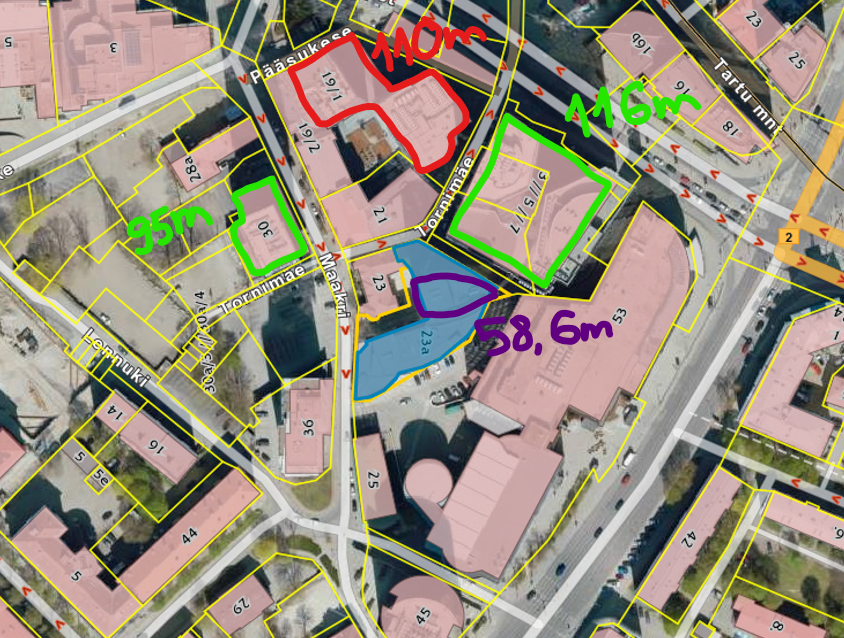
Tegemist on 17-korruselise büroohoonega (kõrgus 58.6 m), mis asub Maakri tänava kõrghoonete piirkonnas. Ümbritsevad hooned on oluliselt kõrgemad (vt. lisa) — Tornimäe 3, 5, 7 (116 m), Maakri 19, 21 (110 m), Maakri 30 (95.1 m) — ning seetõttu paikneb Maakri 23a nende kaitseväljas.
Vastavalt Siseministri määruse nr 17 „Ehitisele esitatavad tuleohutusnõuded“ § 11 lg 2 p 3 sätestatule peab piksekaitse olema hoonel, mille kõrgeim osa ulatub ümbruskonna hoonestusest enam kui 15 m kõrgemale, või mille kasutusotstarve seda eeldab.
Antud hoone ei ulatu ümbruskonna hoonestusest üle nimetatud piirväärtuse ning kasutusotstarve on büroo (mitte majutus- ega rahvahulgaehitis).
Lisaks on Melior Projekt OÜ poolt koostatud piksekaitse riskianalüüs vastavalt EVS-EN 62305-2 metoodikale, mille arvutustulemuste põhjal on riskitase alla lubatud piirväärtuste ning välise piksekaitse rakendamine ei ole vajalik (vt. lisa 2).
Palume Päästekeskuse seisukohta, kas antud juhul võib lähtuda eeltoodud määruse alusel tõdemusest, et välise piksekaitse süsteemi rajamine ei ole nõutav, ning piisab sisemisest liigpingekaitsest (SPD) vastavalt standardile EVS-EN 62305-4.
Lugupidamisega,
/allkirjastatakse digitaalselt/
Sven Mihailov
AS Neutra Capital juhatuse liige
Saatja: Kenneth Karpov <[email protected]>
Saadetud: 15.10.2025 12:03
Adressaat: PÄA Põhja <[email protected]>
Koopia: <[email protected]>
Teema: Päring Maakri 23a
Manused: Pöördumine Pohja Päästekeskusele Maakri 23a.asice; Lisa 1
ümbruskonna hooned.png; Lisa 2 riskianalüüs.asice
TÄHELEPANU! Tegemist on väljastpoolt asutust saabunud kirjaga. Tundmatu
saatja korral palume linke ja faile mitte avada!
Tere,
saadame päringu seoses Maakri 23a hoonega.
--
Lugupidamisega,
Kenneth Karpov
+372 52 598 51

Digiallkirjad
Ehitusprojekt “Maakri 23a hoone laiendamis- ja
rekonstrueerimisprojekt” Ehitusprojekti osa “Piksekaitse riskianalüüs”
[EL1-0-01]
EHITISE AADRESS: Maakri 23a, Kesklinna LO, Tallinn, Harjumaa PROJEKTI TUNNUS: 339
PEAPROJEKTEERIJA: OÜ Fausto Capital Äriregistri kood: 1939341 Kontaktandmed: Aadress: Küütri 8, Tartu 51007, Tartu maakond Vastutav isik: Kenneth Karpov E-mail: [email protected] Kutsetunnistuse nr: -
EHITUSPROJEKTI OSA KOOSTAJA: Melior Projekt OÜ Kontaktandmed: Aadress: Tartu mnt 84a, Kesklinna linnaosa, Tallinn 10112,
Harju maakond Kontaktisik: Maria Aarand Telefon: +372 521 8079 E-mail: [email protected] Äriregistri kood: 11709144 MTR reg. nr: TEL001304, FPR000262
EHITUSPROJEKTI OSA STAADIUM: Põhiprojekt EHITUSPROJEKTI OSA VERSIOON: v01
VÄLJA ANDMISE KUUPÄEV: 2024-04-08 MUUDATUSE KUUPÄEV: - EHITUSPROJEKTI OSA KOOSTAJA: Dmitri Gridin /digiallkiri/ VASTUTAV ISIK: Dmitri Gridin /digiallkiri/ Kutsetunnistuse nr: 135134 (Turvasüsteemide
projekteerija, tase 6); Kutsetunnistuse nr: 155665 (Diplomeeritud
elektriinsener, tase 7);
Muudatuse
tähis
Muudatuse
kuupäev
1 EL-0-01 Tiitelleht 339_PP_EL1-0-01_tiitelleht.pdf 2024-04-08
2 EL-0-03 Dokumentide nimekiri 339_PP_EL1-0-02_dokumentide-nimikiri.pdf 2024-04-08
3 EL-3-01 Seletuskiri 339_PP_EL1-3-01_seletuskiri.pdf 2024-04-08
4 EL-9-01 Riskianalüüsi raport 339_PP_EL1-9-01_v01_riskianalyys-eng.pdf 2024-04-08
Dokumentide nimikiri
Koostamise
kuupäev
Muudatused
Märkused Jrk
nr.
Joonise
nr. Joonise nimetus Faili nimetus
Tunnus: Versioon:
339 v01
Maakri 23a hoone laiendamis- rekonstrueerimisprojekt Tartu mnt 84a Maakri 23a, Kesklinna LO, Tallinn,
Reg nr 11709144 Vastutav
isik: D.Gridin /digiallkiri/
Tallinn 10112
www.meliorprojekt.ee
2024-04-08+3725218079 EL1-0-02
Koostas: D.Gridin /digiallkiri/ PIKSEKAITSE RISKIANALÜÜS
DOKUMENTIDE NIMIKIRIHarjumaa Välja andmise kuupäev; Muudatuse kuupäev: Tähis:Staadium:
Põhiprojekt
1/1
Tartu mnt 84a, Tallinn 10112
+372 52 18 079 Reg.nr.: 11709144
Ehitusprojekti nimi, ehitise aadress: Välja andmise kuupäev / Muudatuse kuupäev:
Maakri 23a hoone laiendamis- rekonstrueerimisprojekt Maakri 23a, Kesklinna LO,
Tallinn, Harjumaa 2024-04-08 / -
www.meliorprojekt.ee [email protected]
Teostas: D. Gridin/(digiallkiri)
Ehitusprojekti osa: PIKSEKAITSE RISKIANALÜÜS
Leht/lehti Kokku: 1 / 4
SELETUSKIRI
Vastutav spetsialist: D. Gridin/(digiallkiri)
Tunnus: Staadium: Versioon: Tähis:
339 PÕHIPROJEKT v01 EL1-3-01
SISUKORD
1. Üldandmed ................................................................................................................................................... 2
1.1 Projekteerimistöö piiritlus.............................................................................................................. 2
1.2 Alusdokumendid ................................................................................................................................. 2
1.2.1 Lähteandmed .................................................................................................................................... 2
1.2.3 Normdokumendid .......................................................................................................................... 2
2. Tuleohutussüsteemid ............................................................................................................................... 3
2.1. Piksekaitse ............................................................................................................................................ 3
2.1.1. Piksekaitsevajadus ........................................................................................................................ 3
2.1.2. Riskianalüüs ..................................................................................................................................... 3
2.1.3. Kokkuvõtte ....................................................................................................................................... 3
Tartu mnt 84a, Tallinn 10112
+372 52 18 079 Reg.nr.: 11709144
Ehitusprojekti nimi, ehitise aadress: Välja andmise kuupäev / Muudatuse kuupäev:
Maakri 23a hoone laiendamis- rekonstrueerimisprojekt Maakri 23a, Kesklinna LO,
Tallinn, Harjumaa 2024-04-08 / -
www.meliorprojekt.ee [email protected]
Teostas: D. Gridin/(digiallkiri)
Ehitusprojekti osa: PIKSEKAITSE RISKIANALÜÜS
Leht/lehti Kokku: 2 / 4
SELETUSKIRI
Vastutav spetsialist: D. Gridin/(digiallkiri)
Tunnus: Staadium: Versioon: Tähis:
339 PÕHIPROJEKT v01 EL1-3-01
1. Üldandmed
1.1 Projekteerimistöö piiritlus
Käesolev projekt käsitleb Tallinnas, Kesklinna LO, Maakri kvartalis Maakri 23a hoone rekonstrueerimist ja laiendamist.
Käesoleva projekti osaga lahendatakse järgmised eriosad:
• Piksekaitse riskianalüüs
Projekti käesolev kaust ei hõlma tugevvoolu, nõrkvoolu ja automaatika töövõttu.
1.2 Alusdokumendid
1.2.1 Lähteandmed
• Tuleohutuse tööprojekt. Rovalis OÜ, töö nr. 22059-TP. Vastutav isik: Martin Seetur
• Arhitektuurne põhiprojekt. KAOS Arhitektid OÜ, töö nr 19-02, Vastutav isik: Margit Aule
1.2.3 Normdokumendid
ÜLDISED:
EVS 932:2017 „Ehitusprojekt“ RTI, 2003, 68, 461 „Turvaseadus“ RTI, 2015 „EHITUSSEADUSTIK“ RTI, 2015 „Seadme ohutuse seadus“ RTI, 07.04.2017, 17 „Ehitisele esitatavad tuleohutusnõuded ja nõuded tuletõrje veevarustusele”
TULEOHUTUS:
EVS-EN 62305-1:2011 “Piksekaitse. Osa 1: Üldpõhimõtted” EVS-EN 62305-2:2013 “Piksekaitse. Osa 2: Riskianalüüs” EVS-EN 62305-3:2011 “Piksekaitse. Osa 3: Ehitistele tekitatavad füüsikalised kahjustused ja oht elule”
Tartu mnt 84a, Tallinn 10112
+372 52 18 079 Reg.nr.: 11709144
Ehitusprojekti nimi, ehitise aadress: Välja andmise kuupäev / Muudatuse kuupäev:
Maakri 23a hoone laiendamis- rekonstrueerimisprojekt Maakri 23a, Kesklinna LO,
Tallinn, Harjumaa 2024-04-08 / -
www.meliorprojekt.ee [email protected]
Teostas: D. Gridin/(digiallkiri)
Ehitusprojekti osa: PIKSEKAITSE RISKIANALÜÜS
Leht/lehti Kokku: 3 / 4
SELETUSKIRI
Vastutav spetsialist: D. Gridin/(digiallkiri)
Tunnus: Staadium: Versioon: Tähis:
339 PÕHIPROJEKT v01 EL1-3-01
2. Tuleohutussüsteemid
Hoone olulised näitajad:
Hoone tulepüsivusklass TP1 Hoone kasutusviis V kasutusviis (kontor); Korruste arv 17 maapealset korrust Hoone kõrgus 58,61 m Põlemiskoormus Tehnilised ruumid, bürooruumid - kuni 600 MJ/m2
Jäätmete ruum, Laoruumid – üle 1200 MJ/m2 Kasutajate arv 865
Rekonstrueeritava hoone ümber asuvad teised kõrghooned, mis on rekonstrueeritavast hoonest kõrgemad. Kõrgemad hooned asuvad aadressitel:
• Tornimäe 5 / 7 • Maakri 36 • Maakri 19/21 • Maakri 30
2.1. Piksekaitse
2.1.1. Piksekaitsevajadus
Piksekaitsevajadus leiakse riskianalüüsi põhjal, mis on teostatud vastavalt standardile EVS- EN 62305-2:2013.
2.1.2. Riskianalüüs
Käesolevaga analüüsiga hinnatakse järgmised riskid:
• R1 - Risk kaotada inimelu (või tekitada püsiv vigastus); Vastuvõetava riski väärtus RT on - 10-5
2.1.3. Kokkuvõtte
Riskianalüüs on teostatud kasutades tarkvara DEHN Risk tool 23/07 (3.260) mis põhineb standardil EN 62305-2. Teostatud riskianalüüs põhineb informatsioonil mis oli saadud teistelt projekti osadelt ja/või Tellijalt.
Tartu mnt 84a, Tallinn 10112
+372 52 18 079 Reg.nr.: 11709144
Ehitusprojekti nimi, ehitise aadress: Välja andmise kuupäev / Muudatuse kuupäev:
Maakri 23a hoone laiendamis- rekonstrueerimisprojekt Maakri 23a, Kesklinna LO,
Tallinn, Harjumaa 2024-04-08 / -
www.meliorprojekt.ee [email protected]
Teostas: D. Gridin/(digiallkiri)
Ehitusprojekti osa: PIKSEKAITSE RISKIANALÜÜS
Leht/lehti Kokku: 4 / 4
SELETUSKIRI
Vastutav spetsialist: D. Gridin/(digiallkiri)
Tunnus: Staadium: Versioon: Tähis:
339 PÕHIPROJEKT v01 EL1-3-01
Pange tähele, et kõik eeldused, dokumendid, illustratsioonid, joonised, mõõtmed, parameetrid ja tulemused ei ole riskianalüüsi tegijale õiguslikult siduvad. Arvutuse tulemused: Vastuvõetava riski väärtus RT 1x 10⁻⁵
Arvutatud risk R1 (kaitsmata) 1,12x 10⁻⁵
Arvutatud risk R1 (kaitstud) 7,76x 10⁻⁶
Vastavalt arvutuse tulemusele arvutatud riski väärtus R1 on väiksem kui vastuvõetava riski väärtus RT , tulenevalt eeltoodust ei ole piksekaitse vajalik. Riskianalüüsi arvutus on toodud lisas (tarkvara piirangu tõttu raport on inglisekeelne).
DEHN Risk Tool 23/07 (3.260) - 08.04.2024 Page 1 of 15
Date: 08.04.2024 Project No.: 04/006
Lightning protection Risk management
Created according to international standard: IEC 62305-2:2010-12
Considering the country-specific annexes for: EN 62305-2:2012-03
Summary of measures for reducing damage caused by lightning effects,
resulting from the risk management concerning the following project:
Project / object description:
Maakri 23a Office Building
Tallinn Estonia
Customer / principal:
Risk assessment by:
D. Gridin
Risk analysis for assessing the risk for structures according to EN 62305-2:2012-03
DEHN Risk Tool 23/07 (3.260) - 08.04.2024 Page 2 of 15
Contents
1. Abbreviations
2. Normative basics
3. Risk and sources of damage
4. Project data 4.1. Selection of risks to be considered 4.2. Geographic and building parameters 4.3. Division of the structure into lightning protection zones/zones
5. Supply lines
6. Properties of the structure 6.1. Risk of fire 6.2. Measures to reduce the consequences of a fire 6.3. Special hazards in the building for persons 6.4. External spatial shielding
7. Risk assessment 7.1. Risk R1, Human life 7.2. Selection of protection measures
8. Legal obligation
9. General information
10. Definition
Risk analysis for assessing the risk for structures according to EN 62305-2:2012-03
DEHN Risk Tool 23/07 (3.260) - 08.04.2024 Page 3 of 15
1. Abbreviations
a Amortisation rate at Amortisation period ca Value of animals in a zone in currency cb Value of a zone of the structure in currency cc Value of the contents of a zone in currency cs Value of the systems in a zone (including their activities) in currency ct Total value of the structure in currency CD;CDJ Location factor CL Annual costs of the total loss without protection measures CPM Annual costs of the selected protection measures CRL Annual costs of the residual loss EB Lightning equipotential bonding H Height of the structure HP Highest point of the structure i Interest rate KS1 Factor relevant to the shielding effectiveness of a structure (external spatial shielding) KS1W Mesh size of the shielding of a structure KS2 Factor relevant to the shielding effectiveness of a structure (external spatial shielding) KS2W Mesh size of the shielding within a structure L1 Loss of human life L2 Loss of service to the public L3 Loss of cultural heritage L4 Loss of economic value L Length of the structure LEMP Lightning electromagnetic impulse LP Lightning protection (consisting of a lightning protection system (LPS) and LEMP
protection measures) LPL Lightning protection level LPS Lightning protection system LPZ Lightning protection zone (zone where the lightning electromagnetic environment is
defined) m Maintenance rates ND Frequency of dangerous events caused by lightning strikes to a structure NG Ground flash density PB Probability that a lightning strike to a structure causes physical damage PEB Lightning equipotential bonding PSPD Coordinated SPD system R Risk R1 Risk of loss of human life in a structure R2 Risk of loss of service to the public R3 Risk of loss of cultural heritage R4 Risk of loss of economical value in a structure RA Risk component (injury to living beings - Lightning strike to the structure) RB Risk component (physical damage to a structure - Lightning strike to the structure)
Risk analysis for assessing the risk for structures according to EN 62305-2:2012-03
DEHN Risk Tool 23/07 (3.260) - 08.04.2024 Page 4 of 15
RC Risk component (failure of internal systems - Lightning strike to the structure) RM Risk component (failure of internal systems - Lightning strike near the structure) RU Risk component (injury to living beings - Lightning strike to a connected supply line) RV Risk component (physical damage to a structure - Lightning strike to a connected supply
line) RW Risk component (failure of internal systems - Lightning strike to a connected supply line) RZ Risk component (failure of internal systems - Lightning strike near the connected supply
line) RT Tolerable risk (maximum value of the risk which can be tolerated for the structure to be
protected) rf Reduction factor considering the fire risk in a structure rp Reduction factor considering the measures to reduce the consequences of a fire SM Annual savings SPD Surge protection device SPM LEMP protection measures (measures to reduce the risk of failure of electrical and
electronic equipment due to LEMP) tex Duration of the presence of a dangerous explosive atmosphere W Width of the structure Z Zones of a structure
2. Normative basics
The EN 62305 standard series consists of the following parts:
- EN 62305-1:2011-02 - "Protection against lightning - Part 1: General principles“
- EN 62305-2:2012-03 - "Protection against lightning - Part 2: Risk management"
- EN 62305-3:2011-02 - "Protection against lightning - Part 3: Physical damage to structures and life hazard“
- EN 62305-4:2011-02 - "Protection against lightning - Part 4: Electrical and electronic systems within structures“
3. Risk and sources of damage
In order to avoid damage resulting from a lightning strike, specific protection measures must be taken for the objects to be protected. The risk management described in the EN 62305-2:2012-03 standard includes a risk analysis which allows to determine the lightning protection requirements of a structure. The aim of the risk management is to reduce the risk to an acceptable level by taking protection measures.
To determine the prevailing risk, the relevant object must be connsidered without any protection measures (actual condition). Risks that may be caused as a result of direct / indirect lightning strikes to the structure and supply lines are referred to as risk R. The risk defines the possible annual loss. Risks that must be assessed for a structure could be:
• Risk R1: risk of loss of human life; • Risk R2: risk of loss of services to the public; • Risk R3: risk of loss of cultural heritage; • Risk R4: risk of loss of economic value;
Risk analysis for assessing the risk for structures according to EN 62305-2:2012-03
DEHN Risk Tool 23/07 (3.260) - 08.04.2024 Page 5 of 15
All risks or the individual risks must be assessed depending on the type of consideration. Every risk is defined with a tolerable risk in form of a numerical value. To achieve a tolerable risk, technically and economically sound protection measures are defined e.g. external lightning protection measures according to EN 62305-3:2011-02 and SPD measures according to EN 62305-4:2011-02.
To be able to determine the risk focus more exactly, the risks are considered in detail. Every risk consists of a sum of risk components.
• R1 = RA + RB + RC + RM + RU + RV + RW + RZ • R2 = RB + RC + RM + RV + RW + RZ • R3 = RB + RV • R4 = RA + RB + RC + RM + RU + RV + RW + RZ
Every risk component describes a certain danger and thus a possible loss. The loss resulting from lightning effects is defined as follows:
• L1 = Loss of human life • L2 = Loss of service to the public • L3 = Loss of cultural heritage • L4 = Loss of economic value
The possible loss is assigned to the risk components as follows:
The risk components are differentiated according to the sources of damage.
Source of damage S1: Risk components based on lightning strikes to the structure
RA Component which refers to injury of living beings caused by an electric shock resulting from touch and step voltage within the structure and up to 3 m around the down conductors outside the structure. Type of damage L1 may occur for agricultural buildings and type of damage L4 with possible loss of animals.
RB Component which refers to physical damage caused by dangerous sparking within the structure resulting in fire and explosion. Even the environment can be at risk. All types of damage can occur (L1, L2, L3, L4).
Risk analysis for assessing the risk for structures according to EN 62305-2:2012-03
DEHN Risk Tool 23/07 (3.260) - 08.04.2024 Page 6 of 15
RC Component which refers to the failure of internal systems caused by LEMP. Types of damage L2 and L4 can occur in all cases and type of damage L1 in case of structures with a risk of explosion and hospitals or other structures in which the failure of internal systems can be lead to loss of human life.
Source of damage S2: Risk components for a structure as a result of lightning strikes near the structure
RM Component which refers to the failure of internal systems caused by LEMP. Types of damage L2 and L4 can occur in all cases and type of damage L1 in case of structures with a risk of explosion and hospitals or other structures in which the failure of internal systems can be lead to loss of human life.
Source of damage S3: Risk components for a structure as a result of lighting strikes to the incoming supply line
RU Component which refers to injury of living beings caused by an electric shock resulting from touch voltage within the structure. Type of damage L1 may occur for agriculture facilities and type of damage L4 with possible loss of animals.
RV Component which refers to physical damage caused by the lightning current injected into the structure by means of or along the supply line (fire or explosion due to dangerous sparking between the external installation and the metal parts, typically at the point where the supply line enters the structure). All types of damage (L1, L2, L3, L4) can occur.
RW Component which refers to the failure of internal systems caused by overvoltages injected into the structure by means of incoming supply lines. Types of damage L2 and L4 can occur in all cases and type of damage L1 in case of structures with a risk of explosion and hospitals or other structures in which the failure of internal systems can be lead to loss of human life.
Source of damage S4: Risk components for a structure as a result of lighting strikes near the incoming supply line
RZ Component which refers to the failure of internal systems caused by overvoltages injected into the structure by means of incoming supply lines. Types of damage L2 and L4 can occur in all cases and type of damage L1 in case of structures with a risk of explosion and hospitals or other structures in which the failure of internal systems can be lead to loss of human life.
The risk components allow to analyse the risks and measures to avoid possible loss can be taken.
The following risk analysis according to EN 62305-2:2012-03 for the project Maakri 23a Office Building - object Maakri 23a Office Building shows the necessity of protection measures. The risk potential for the structure is determined and, if necessary, measures to reduce the risk have to be taken. The result of the risk analysis not only specifies the class of LPS, but also provides a complete protection concept including the necessary LEMP protection measures.
As a result, an economically reasonable selection of protection measures suitable for the properties and
Risk analysis for assessing the risk for structures according to EN 62305-2:2012-03
DEHN Risk Tool 23/07 (3.260) - 08.04.2024 Page 7 of 15
use of the structure is ensured.
4. Project data
4.1 Selection of risks to be considered
Due to the type and use of the structure, object Maakri 23a Office Building, the following risks were selected and considered:
Risk R1: Risk of losses of human life; RT: 1,00E-05
The tolerable risks RT were defined by selecting the risks.
The aim of a risk analysis is to reduce the risk to a acceptable level RT by an economically sound selection of protection measures.
4.2 Geographic and building parameters
The ground flash density Ng is the basis for a risk analysis according to EN 62305-2:2012-03. It defines the number of direct lightning strikes in 1 / year / km². A value of 1,86 lightning strikes / year / km² was determined for the location of the object Maakri 23a Office Building by means of the ground flash density map. As a result, there is a calculated number of 18,60 of thunderstorm days per year for the location of the project.
The dimensions of the building are decisive for the risk of a direct strike. The collection areas for direct / indirect lightning strikes are determined based on it's dimensions. This results in a calculated collection area for direct lightning strikes of 119 145,00 m² and for indirect lightning strikes (near the structure) of 894 503,00 m².
Risk analysis for assessing the risk for structures according to EN 62305-2:2012-03
DEHN Risk Tool 23/07 (3.260) - 08.04.2024 Page 8 of 15
The environment surrounding the structure is an important factor for determining the number of direct / indirect lightning strikes. It was defined as follows for the building Maakri 23a Office Building: Relative location Cdb: 0,25
If the ground flash density is referred to the size and the environment of the structure, a frequency of direct strikes Nd to the structure of 0,0554 strikes / year and indirect strikes near the structure of 1,6638 strikes / year is to be expected.
4.3 Division of the structure into lightning protection zones/zones
The structure Maakri 23a Office Building was not divided into lightning protection zones / zones.
L1tz – Time during which persons are present in the zone.: 8 760 hours/year L1nz – Number of persons in the zone: 0 persons
5. Supply lines
All incoming and outgoing supply lines of the structure to be considered must be taken into account in the risk analysis. Conductive pipes do not have to be considered if they are connected to the main earthing busbar of the structure. If this is not the case, the risk of incoming pipes should be considered in the risk analysis (observe that equipotential bonding is required!).
The following supply lines were considered for the structure Maakri 23a Office Building in the risk analysis:
- Conductor 1 - Conductor 2
5.1 Conductor 1
Installation factor: Buried
Type of conductor: Power supply line
Environment: Urban
Connection of the conductor:
No special conditions
Transformer: HV power supply line (with HV/LV transformer)
Conductor shielding: External: Aerial or unshielded buried cable
The conductor length outside the structure up to the next node is 1 000,00 m.
Based on this, the following collection areas were determined for the supply line: - Collection area for direct lightning strikes to a supply line: 40 000,00 m² - Collection area for indirect lightning strikes near a supply line: 4 000 000,00 m²
Risk analysis for assessing the risk for structures according to EN 62305-2:2012-03
DEHN Risk Tool 23/07 (3.260) - 08.04.2024 Page 9 of 15
The dielectric strength of the electrical equipment which is connected with the Conductor 1 is Uw <= 1.0 kV
The conductors in the building are installed via Unshielded cable – no routing precaution in order to avoid loops.
5.2 Conductor 2
Installation factor: Buried
Type of conductor: Telecommunication line
Environment: Urban
Connection of the conductor:
Connection via isolating interface
Transformer: LV power supply, telecommunication or data line
Conductor shielding: External: Aerial or unshielded buried cable
The conductor length outside the structure up to the next node is 1 000,00 m.
Based on this, the following collection areas were determined for the supply line: - Collection area for direct lightning strikes to a supply line: 40 000,00 m² - Collection area for indirect lightning strikes near a supply line: 4 000 000,00 m²
The dielectric strength of the electrical equipment which is connected with the Conductor 2 is 1.0 kV < Uw <= 1.5 kV
The conductors in the building are installed via Unshielded cable – no routing precaution in order to avoid loops.
6. Properties of the structure
6.1 Risk of fire
The risk of fire is one of the most important criteria for determining whether an LPS (lightning protection system) must be installed. The risk of fire is classified according to the specific fire load. The fire load should be determined by a fire safety expert or defined after consultation with the proprietor of the building and his / her insurance company. A distinction is made according to the following criteria:
None Low (specific fire load in the building less than 400 MJ/m²) Ordinary (specific fire load in the building between 400 MJ/m² and 800 MJ/m²) High (specific fire load in the building greater than 800 MJ/m²) Explosion: zone 2 / 22 Explosion: zone 1 / 21 Explosion: zone 0 / 20
Risk analysis for assessing the risk for structures according to EN 62305-2:2012-03
DEHN Risk Tool 23/07 (3.260) - 08.04.2024 Page 10 of 15
The risk of fire in a structure is an important factor for determining the required protection measures. The risk of fire for the structure Maakri 23a Office Building was defined as follows:
- Normal risk of fire
6.2 Measures to reduce the consequences of a fire
The following measures were selected to reduce the consequences of a fire:
- Automatic fire extinguishing system/fire alarm system
6.3 Special hazards in the building for persons
Due to the number of persons, the possible risk of panic for the structure Maakri 23a Office Building was defined as follows:
- No special hazard
6.4 External spatial shielding
Spatial shielding attenuates the magnetic field within a structure caused by lightning strikes to or near the object and reduces internal surges. This can be achieved by an intermeshed equipotential bonding network in which all conductive parts of the structure and the internal systems are integrated. Consequently, the external / internal spatial shield is only a part of a shielded building structure. It must be observed that metal coverings and claddings are connected to one another and conductively to the equipotential bonding of the building. In this context, the relevant normative requirements must be observed.
Covering of the structure Maakri 23a Office Building:
- No shielding
7. Risk assessment
As described in 4.1, the following risks according to 7.were assessed. The blue bar shows the tolerable risk value and the green / red bar shows the risk determined.
7.1 Risk R1, Human life
The following risk was determined for persons outside and inside the structure Maakri 23a Office Building:
Tolerable risk RT: 1,00E-05 Calculated risk R1 (unprotected): 1,12E-05
Calculated risk R1 (protected): 7,76E-06
Risk analysis for assessing the risk for structures according to EN 62305-2:2012-03
DEHN Risk Tool 23/07 (3.260) - 08.04.2024 Page 11 of 15
The risk R1 consists of following risk components:
To reduce the risk, it is necessary to take measures as described in 7.
7.2 Selection of protection measures
The risk was reduced to an acceptable level by selecting the following protection measures.
This selection of protection measures is part of the risk management for the object Maakri 23a Office Building and is only valid in connection with this object.
Measures With protection/target state:
Area Measures Factor
pEB: Lightning equipotential bonding Equipotential bonding for LPL I 1.000E-02
ra: External characteristics of the ground/floor Agriculturally used area, concrete R <= 1 kOhm
1.000E-02
ru: Internal characteristics of the ground/floor Agriculturally used area, concrete R <= 1 kOhm
1.000E-02
rp: Fire precautions Automatic fire extinguishing system/fire alarm system
2.000E-01
Risk analysis for assessing the risk for structures according to EN 62305-2:2012-03
DEHN Risk Tool 23/07 (3.260) - 08.04.2024 Page 12 of 15
8. Legal obligation
The risk analysis performed refers to the information provided by the operator and/or proprietor of the building or expert which has been assumed, assessed or defined on site. Please note that this information must be verified after assessment.
The procedure of the DEHNsupport software for calculating the risks is based on the EN 62305-2:2012-03 standard.
Please note that all assumptions, documents, illustrations, drawings, dimensions, parameters and results are not legally binding for the person performing the risk analysis.
_____________________________________ _____________________________________ Place, date Stamp, signature
Risk analysis for assessing the risk for structures according to EN 62305-2:2012-03
DEHN Risk Tool 23/07 (3.260) - 08.04.2024 Page 13 of 15
9. General information
9.1 Components of the external lightning protection system Lightning protection components used for the construction of the external lightning protection system must comply with the mechanical and electrical requirements defined in the EN 62561-x standard series. This standard series is for example divided into following parts:
- EN 62561-1:2012 Requirements for connection components - EN 62561-2:2012 Requirements for conductors and earth electrodes - EN 62561-3:2012 Requirements for isolating spark gaps - EN 62561-4:2011 Requirements for conductor fasteners - EN 62561-5:2011 Requirements for electrode inspection housings and earth
electrode seals
9.1.1 EN 62561-1:2012 Requirements for connection components The requirements for connection components such as clamps are defined in EN 62561-1. For the installer of lightning protection systems this means that the connection components are to be selected for the load (H or N) to be expected at the place of installation. Therefore, a clamp for load H (100 kA) is to be used e.g. for an air-termination rod (100% lightning current) and a clamp for load N (50 kA) e.g. for a mesh or an earth entry (lightning current already distributed). The suitability for these applications must be proven by the manufacturer.
9.1.2 EN 62561-2:2012 Requirements for conductors and earth electrodes The EN 62561-2 specifies concrete requirements for conductors, such as air-termination and down conductors as well as earth electrodes. These are defined as follows: - Mechanical properties (minimum tensile strength and elongation), - Electrical properties (maximum resistivity) and - Corrosion protection properties (artificial aging).
The EN 62561-2 standard also specifies the requirements for earth electrodes and earth rods. In this context, the material, geometry, minimum dimensions as well as the mechanical and electrical properties are important. These normative requirements are relevant product features, which must be documented in the manufacturers' documents and product datasheets.
9.1.3 EN 62561-3:2012 Requirements for isolating spark gaps Isolating spark gaps can be used to galvanically isolate an earth-termination system.EN 62561-3 specifies that isolating spark gaps must be dimensioned in such a way that the components, if installed according to the manufacturer's instructions, are reliable, durable and safe for persons and nearby installations.
9.1.4 EN 62561-4:2011 Requirements for conductor fasteners The EN 62561-4 standard specifies the requirements and tests for metal and non-metal conductor fasteners used with air-termination and down conductors.
9.1.5 EN 62561-5:2011 Requirements for electrode inspection housings and earth electrode seals All earth electrode inspection housings and earth electrode seals must be designed in such a way that they are reliable and safe for persons and the environment when used as intended. EN 62561-5 specifies the requirements and tests for earth electrode inspection housings (e.g. pressure load) and for earth electrode seals (e.g. leak test).
10. Definition
Coordinated SPD system
Risk analysis for assessing the risk for structures according to EN 62305-2:2012-03
DEHN Risk Tool 23/07 (3.260) - 08.04.2024 Page 14 of 15
SPDs properly selected, coordinated and installed to form a system intended to reduce failures of electrical and electronic systems.
Isolating interfaces Devices which are capable of reducing conducted surges on lines entering the LPZ. These include isolation transformers with earthed screen between windings, metal-free fibre optic cables and opto-isolators. Insulation withstand characteristics of these devices are suitable for this application intrinsically or via SPD.
LEMP (lightning electromagnetic impulse) All electromagnetic effects of lightning current via resistive, inductive and capacitive coupling, which create surges and electromagnetic fields.
LP (lightning protection) Complete system for protection of structures against lightning, including their internal systems and contents, as well as persons, in general consisting of an LPS and SPM.
LPL (lightning protection level) Number related to a set of lightning current parameters values relevant to the probability that the associated maximum and minimum design values will not be exceeded in naturally occurring lightning.
LPS (lightning protection system) Complete system used to reduce physical damage due to lightning flashes to a structure.
EB (lightning equipotential bonding) Bonding to LPS of separated metallic parts, by direct conductive connections or via surge protective devices, to reduce potential differences caused by lightning current.
SPD (surge protection device) Device intended to limit transient overvoltages and divert surge currents; contains at least one non-linear component.
Node Point on a line from which onward surge propagation can be assumed to be neglected. Examples of nodes are a point on a power line branch distribution at an HV / LV transformer or on a power substation, a telecommunication exchange or an equipment (e.g. multiplexer or xDSL equipment) on a telecommunication line.
Physical damage Damage to a structure (or to its contents) due to mechanical, thermal, chemical or explosive effects of lightning.
Injury to living beings Permanent injuries, including loss of life, to people or to animals by electric shock due to touch and step voltages caused by lightning.
Risk R Value of probable average annual loss (humans and goods) due to lightning, relative to the total value (humans and goods) of the structure to be protected.
Zone of a structure ZS Part of a structure with homogeneous characteristics where only one set of parameters is involved in assessment of a risk component.
Risk analysis for assessing the risk for structures according to EN 62305-2:2012-03
DEHN Risk Tool 23/07 (3.260) - 08.04.2024 Page 15 of 15
LPZ (lightning protection zone) Zone where the lightning electromagnetic environment is defined. The zone boundaries of an LPZ are not necessarily physical boundaries (e.g. walls, floor and ceiling).
Magnetic shield Closed, metallic, grid-like or continuous screen enveloping the structure to be protected, or part of it, used to reduce failures of electrical and electronic systems.
Lightning protective cable Special cable with increased dielectric strength and whose metallic sheath is in continuous contact with the soil either directly or by use of conducting plastic covering.
Lightning protective cable duct Cable duct of low resistivity in contact with the soil (concrete with interconnected structural steel reinforcements or metallic duct).
Digiallkirjad
Päästeamet
Põhja päästekeskus
Erika tn 3, 10416 Tallinn
15.10.2025
Pöördumine Põhja Päästekeskusele
Teema: Piksekaitse vajalikkus hoonel Maakri 23a, Tallinn
Lugupeetud Põhja Päästekeskus,
Seoses hoone Maakri 23a, Tallinn kasutusloa taotlusega palume Teie seisukohta välise piksekaitse süsteemi (LPS) vajaduse kohta.
Tegemist on 17-korruselise büroohoonega (kõrgus 58.6 m), mis asub Maakri tänava kõrghoonete piirkonnas. Ümbritsevad hooned on oluliselt kõrgemad (vt. lisa) — Tornimäe 3, 5, 7 (116 m), Maakri 19, 21 (110 m), Maakri 30 (95.1 m) — ning seetõttu paikneb Maakri 23a nende kaitseväljas.
Vastavalt Siseministri määruse nr 17 „Ehitisele esitatavad tuleohutusnõuded“ § 11 lg 2 p 3 sätestatule peab piksekaitse olema hoonel, mille kõrgeim osa ulatub ümbruskonna hoonestusest enam kui 15 m kõrgemale, või mille kasutusotstarve seda eeldab.
Antud hoone ei ulatu ümbruskonna hoonestusest üle nimetatud piirväärtuse ning kasutusotstarve on büroo (mitte majutus- ega rahvahulgaehitis).
Lisaks on Melior Projekt OÜ poolt koostatud piksekaitse riskianalüüs vastavalt EVS-EN 62305-2 metoodikale, mille arvutustulemuste põhjal on riskitase alla lubatud piirväärtuste ning välise piksekaitse rakendamine ei ole vajalik (vt. lisa 2).
Palume Päästekeskuse seisukohta, kas antud juhul võib lähtuda eeltoodud määruse alusel tõdemusest, et välise piksekaitse süsteemi rajamine ei ole nõutav, ning piisab sisemisest liigpingekaitsest (SPD) vastavalt standardile EVS-EN 62305-4.
Lugupidamisega,
/allkirjastatakse digitaalselt/
Sven Mihailov
AS Neutra Capital juhatuse liige